Electrical card connector

a technology of electrical card connectors and connectors, applied in the direction of coupling device connections, coupling parts engagement/disengagement, two-part coupling devices, etc., can solve the problem of higher manufacturing cos

Inactive Publication Date: 2006-10-10
HON HAI PRECISION IND CO LTD
View PDF6 Cites 13 Cited by
  • Summary
  • Abstract
  • Description
  • Claims
  • Application Information

AI Technical Summary

Benefits of technology

[0006]Accordingly, an objection of the present invention is to provide an electrical card connector which saves horizontal space above a printed circuit board on which the electrical card connector is mounted.
[0007]Another objection of the present invention is to provide an electrical card connector which is directly connected on the printed circuit board without a transition connector and conveniently assembled and disassembled.

Problems solved by technology

However, the electrical card connector assembly needs a transition connector mounted on a PCB for connecting the electrical card connector to the PCB, as a result, more vertical space is occupied by the transition connector and further the manufacturing cost is higher.

Method used


Image

  • Electrical card connector
  • Electrical card connector
  • Electrical card connector

Examples


Embodiment Construction

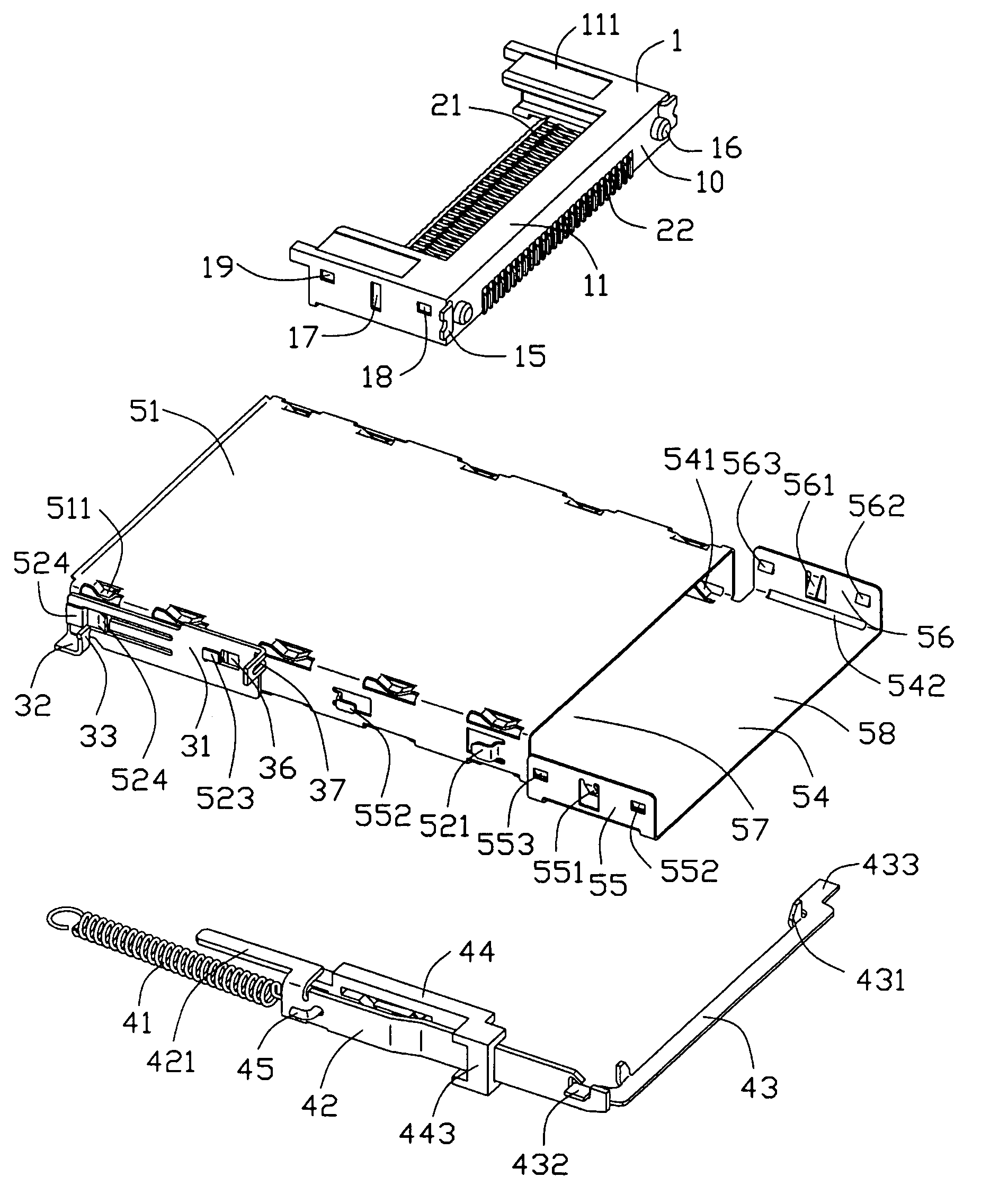
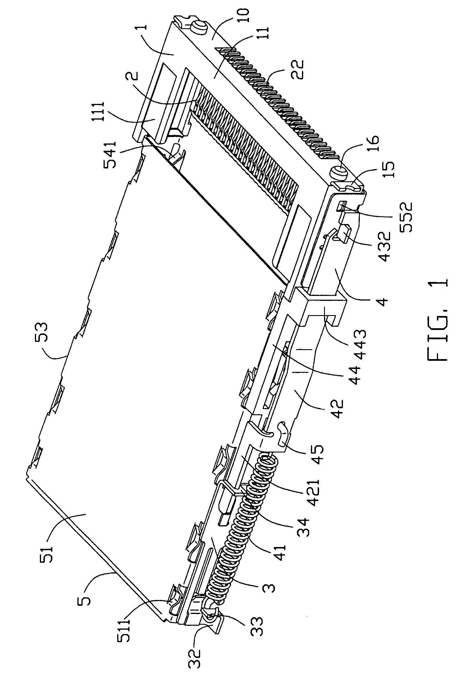
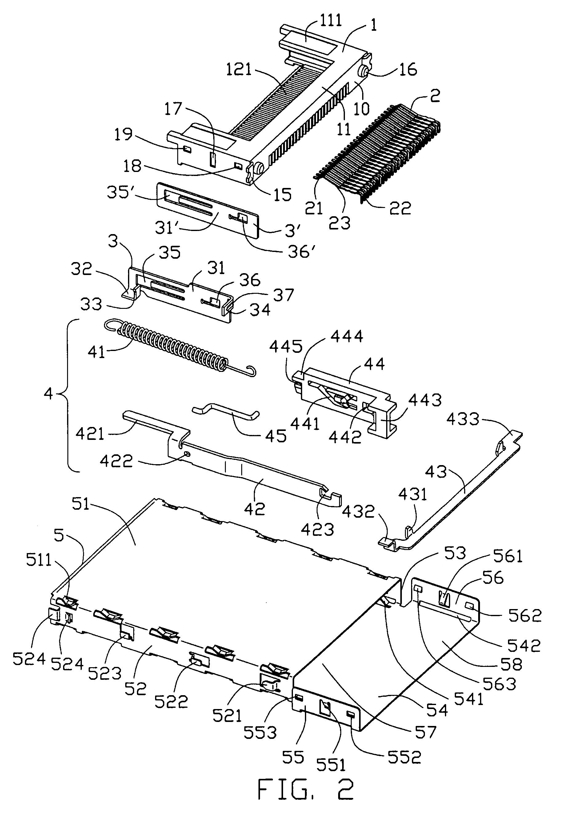
[0016]Referring to FIGS. 1 and 2, an electrical card connector in accordance with the present invention comprises an insulating header 1, a plurality of electrical contacts 2 retained in the insulating header 1, a metallic shell 5 assembled to the insulating header 1, a pair of stand-off devices 3, 3′ secured on opposite sides of the metallic shell 5, and an ejector 4 attached to one side of the metallic shell 5 for ejecting an inserted electronic card (not shown) therefrom.

[0017]Combining with FIG. 5, the insulating header 1 has a longitudinal base 11, a pair of guiding arms 111 extending backwards from two opposite longitudinal ends of the longitudinal base 11 and a card engaging section 12 protruding backwards from a middle of the longitudinal base 11. The longitudinal base 11 has a mounting face 10 perpendicular to the guiding arms 111 and the card engaging section 12. The card engaging section 12 defines a plurality of passageways 121 extending through the mounting face 10 for ...


PUM


Abstract

An electrical card connector comprises an insulating header (1) having a mounting face (10), a plurality of electrical contacts (2) retained in the insulating header (1) and each having a soldering portion (22) arranging along the mounting face (10) and an engaging portion (21) for electrically connecting with an inserted electronic card, and a metallic shell (5) defining a receiving room (57) with an opening (59), through which the electronic card is inserted into the receiving room (57) along a direction, and further having a metallic header (58) disposed at a longitudinal end of the receiving room (57) and far from the opening (59), which is assembled onto the insulating header (1). Wherein the card inserting direction is perpendicular to the mounting face (10).

Description

BACKGROUND OF THE INVENTION[0001]1. Field of the Invention[0002]The present invention generally relates to an electrical card connector, and in particular to an electrical card connector for perpendicularly electrically connecting a card with a printed circuit board.[0003]2. Description of Related Art[0004]Generally, a conventional card connector is parallelly assembled on a printed circuit board (PCB), that is, the insertion of an inserted card is parallel with the PCB, as a result, the card connector occupies a large horizontal space above the PCB. In order to save horizontal space above a PCB, an electrical card connector perpendicularly assembled on the PCB is disclosed, such as an electrical card connector assembly disclosed in U.S. Pat. No. 6,773,273. However, the electrical card connector assembly needs a transition connector mounted on a PCB for connecting the electrical card connector to the PCB, as a result, more vertical space is occupied by the transition connector and f...

Claims


Application Information

Patent Timeline
Patent Type & Authority Patents(United States)
IPC IPC(8): H01R13/62H01R13/648H01R12/00H01R12/71H01R12/72H01R12/73H01R13/635H01R13/658
CPCH01R12/718H01R13/6581H01R13/635
Inventor TING, CHIEN JEN
Owner HON HAI PRECISION IND CO LTD
Why Eureka
Try Eureka