Vertical cable management rack

a vertical cable and rack technology, applied in the field of racks, can solve the problems of small openings that are often insufficient to handle, weiss designs suffer from a number of drawbacks, and the size of the openings is relatively limited

Inactive Publication Date: 2006-10-10
CHATSWORTH PROD INC
View PDF47 Cites 135 Cited by
  • Summary
  • Abstract
  • Description
  • Claims
  • Application Information

AI Technical Summary

Benefits of technology

[0012]Briefly summarized, the present invention relates to vertical cable raceways for precisely routing cables to electronic components at particular elevations in a cabinet, frame or other mounting rack. Broadly defined, the cable raceway according to one aspect of the present invention includes: a trough having a base member and two side members; and at least one separable cable guide installed on the edge of a side member, the cable guide including a plurality of projections forming cable rings for guiding cables laterally from the side of the trough.

Problems solved by technology

Unfortunately, both the Caveney and the Weiss designs suffer from a number of drawbacks, including most particularly the relatively limited size of the openings.
Such small openings are frequently inadequate to handle the large number of cables that are frequently routed horizontally from a certain elevation on a vertical raceway to the equipment mounted thereon.
Further, if a cover is to be installed on the Caveney or Weiss raceways, it must be carefully aligned with all of the distal ends of the projections and pressed into place, and no provision is made to allow the cover to be hinged open once installed.
Unfortunately, because so few projections are available for the cables to be routed around, this type of raceway does not allow cables to be routed as precisely as with the Caveney and Weiss type of raceway, there is a much greater chance of cables dangling loosely, and / or cables of greater length must be used in order to reach a projection before being bent toward the desired equipment.
Barbs at the distal ends of the fingers limit access to the slits to only a narrow gap, thereby preventing cables which have been installed in the slits from accidentally becoming dislodged.
Unfortunately, the Panduit raceway still suffers from a number of drawbacks.
First, once fingers are broken off of the Panduit raceway to create larger openings, they cannot be replaced.
Further, if one or more fingers is broken off to create a larger opening, the gap between the fingers which remain to define the opening is quite large, with very little material or structure remaining to retain the cables in the opening, other than the raceway cover.
Also, the Panduit cover may be attached only using hinge members which are each mounted on the distal ends of a pair of adjacent fingers, rather than to the trough itself, thus increasing the risk of mechanical failure, particularly as the cover is opened and closed.
In addition, the unibody construction limits the installation flexibility otherwise available if the projections could be selectively disposed at various locations along the raceway without affecting the body of the raceway itself.
Perhaps most significantly, none of the cable rings formed in the sides of known prior art raceways are arranged to align precisely with the equipment mounting locations on the racks to which the raceways are attached.
Unfortunately, none of the known prior art raceways take this arrangement into consideration.
Thus, the cable rings or similar structures provided on prior art vertical raceways are not properly aligned with the equipment and accessories to which they must route the cables.
As a result, the shortest path from the interior of the raceway to the equipment or accessory destination is frequently blocked by the body of one of the finger-like projections.
Moreover, smaller components and accessories may not have any cable rings whatsoever disposed next to them.
For high density wiring routes, cable rings may become unnecessarily overcrowded because they must be diverted through other cable rings.

Method used


Image

  • Vertical cable management rack
  • Vertical cable management rack
  • Vertical cable management rack

Examples


Embodiment Construction

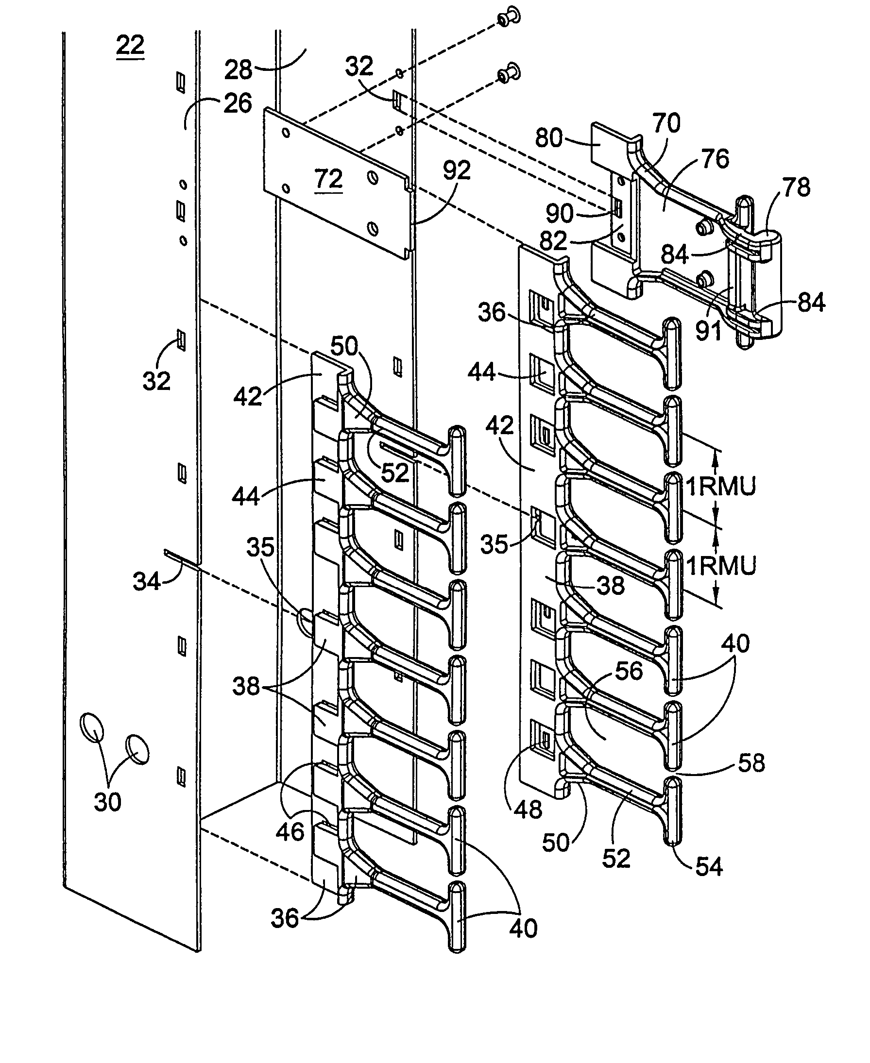
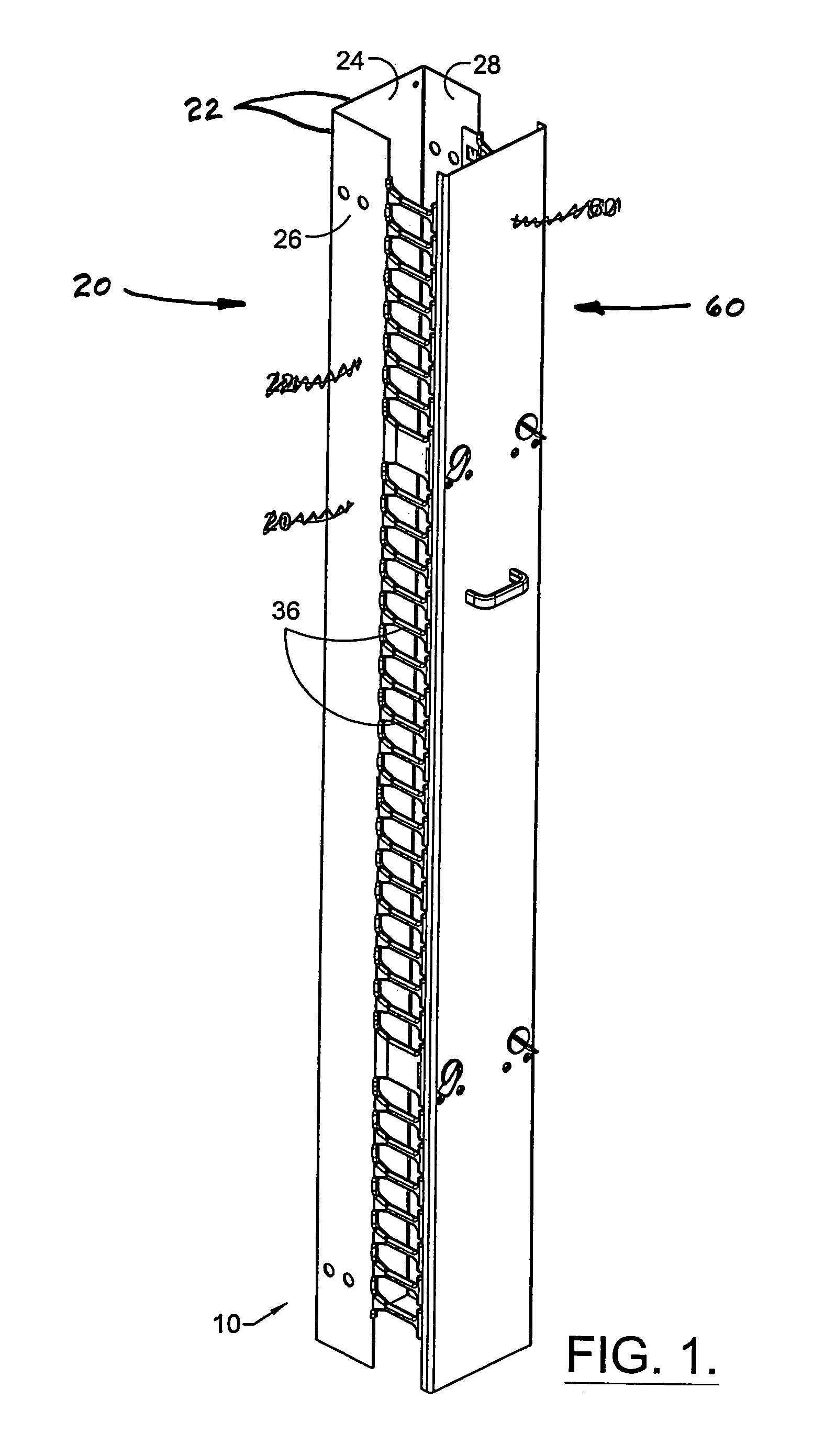
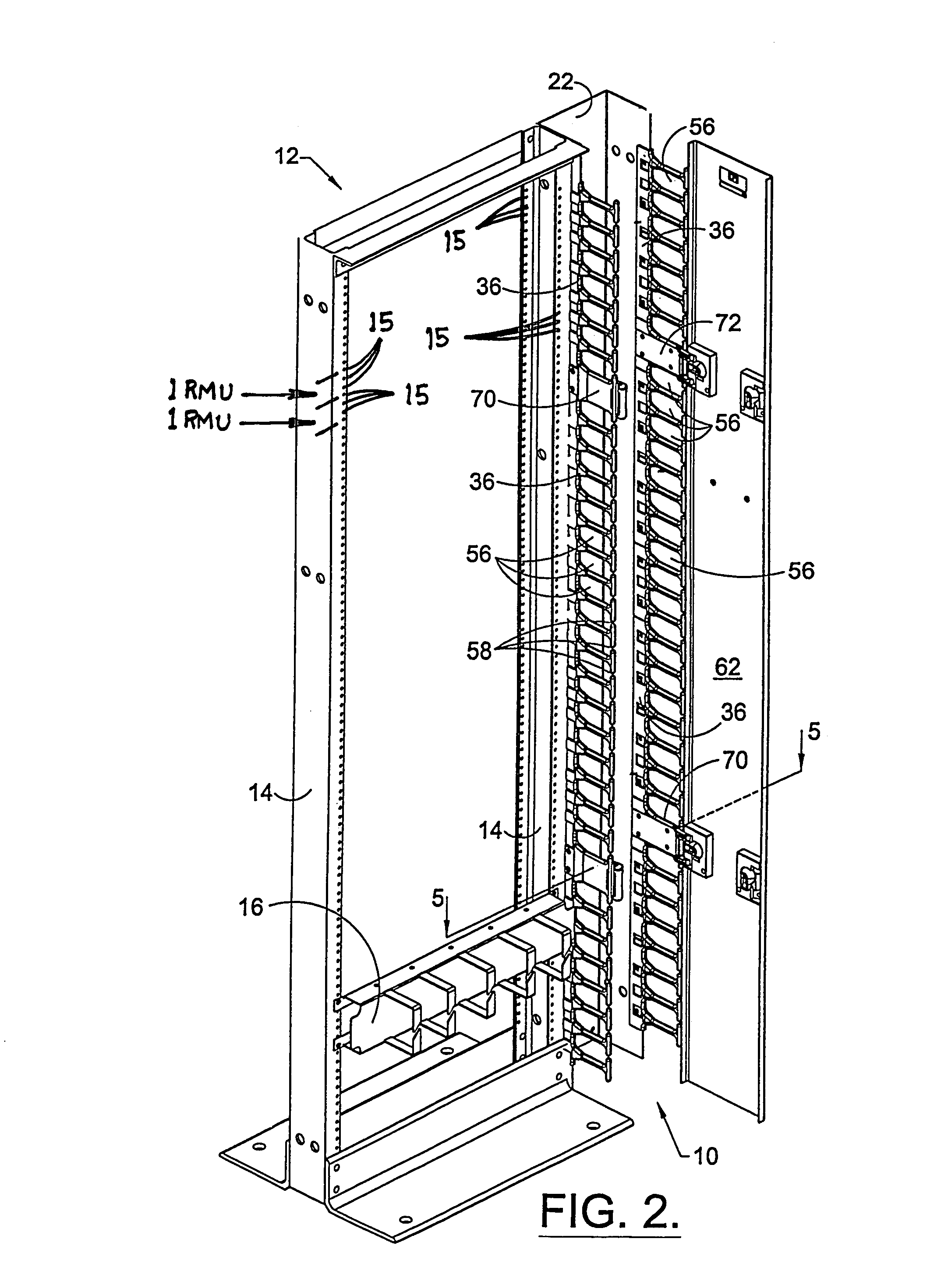
[0037]FIG. 1 is a perspective view of a vertical cable raceway 10 in accordance with a first preferred embodiment of the present invention. In this embodiment, the vertical cable raceway 10 comprises a channel assembly 20 and a cover assembly 60. The channel assembly 20 includes a trough 22 and a plurality of cable guides 36. The trough 22 has a base member 24 and two side members 26, 28 extending perpendicularly therefrom. The trough 22 may be formed from a sheet of suitable metal, such as aluminum or steel, and bent into shape, or it may be machined or extruded from a suitable metal material. As perhaps best illustrated in FIG. 3, each side member 26, 28 includes a plurality of circular apertures 30 for mounting the trough 22 to a rack 12, frame, cabinet or the like, as shown in FIG. 2, and an evenly-spaced series of small rectangular apertures 32 extending along its outer edge for mounting the cable guides 36 thereto.

[0038]FIG. 3 is an exploded perspective view of a portion of th...


PUM


Abstract

A rack for mounting electronic equipment includes a pair of vertical support members having a regular pattern of mounting apertures that repeats linearly at a regular interval and a vertically-oriented cable guide, disposed generally adjacent one of the support members, having a plurality of outwardly-extending projections forming cable rings. The cable rings are disposed along the length of the cable guide at a second regular interval that is a whole number multiple of the first regular interval.

Description

CROSS REFERENCE TO RELATED APPLICATIONS[0001]This application is a continuation of and thus is entitled to the benefit of, and claims priority to, U.S. Pat. application Ser. No. 10 / 192,896, filed Jul. 11, 2002 now U.S. Pat. No. 6,605,782 and entitled “VERTICAL CABLE MANAGEMENT RACK,” which is a divisional of U.S. Pat. application Ser. No. 09 / 954,344, filed Sep. 17, 2001, now U.S. Pat. No. 6,489,565 and entitled “VERTICAL CABLE MANAGEMENT RACK,” which claims the benefit of U.S. Provisional Application Serial No. 60 / 233,203, filed Sep. 15, 2000 and entitled “VERTICAL CABLE MANAGEMENT RACK.” The entirety of each of these applications is hereby incorporated by reference.FIELD OF THE PRESENT INVENTION[0002]The present invention relates generally to the field of racks for supporting computer and other electronic equipment, and more particularly to the field of enclosed vertical cable raceways having a multitude of cable rings formed in the sides thereof for precisely routing cables and wi...

Claims


Application Information

Patent Timeline
Patent Type & Authority Patents(United States)
IPC IPC(8): H02G3/04H04Q1/02H04Q1/06
CPCH02G3/045H04Q1/064H04Q1/062H04Q1/02H04Q2201/02
Inventor KRIETZMAN, WILLIAM DREWBALLESTEROS, ENRIE RILLOMELAMED, BRYAN JOEL
Owner CHATSWORTH PROD INC
Why Eureka
Try Eureka