
Logic cell with improved multiplexer, barrel shifter, and crossbarring efficiency

Inactive Publication Date: 2006-10-10
ALTERA CORP
View PDF3 Cites 19 Cited by
  • Summary
  • Abstract
  • Description
  • Claims
  • Application Information

AI Technical Summary

Benefits of technology

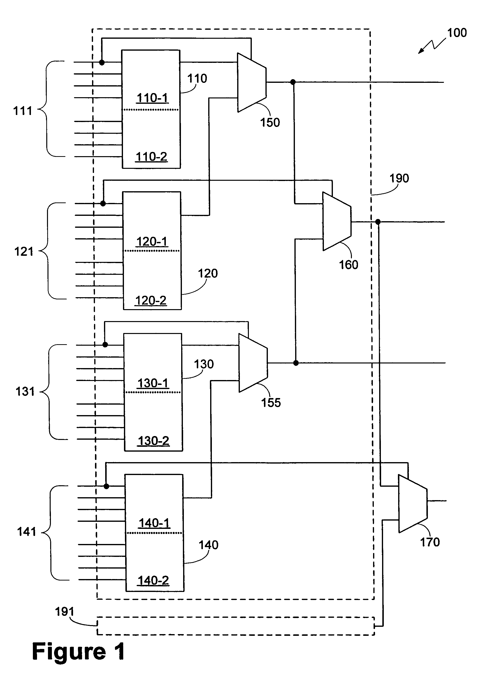
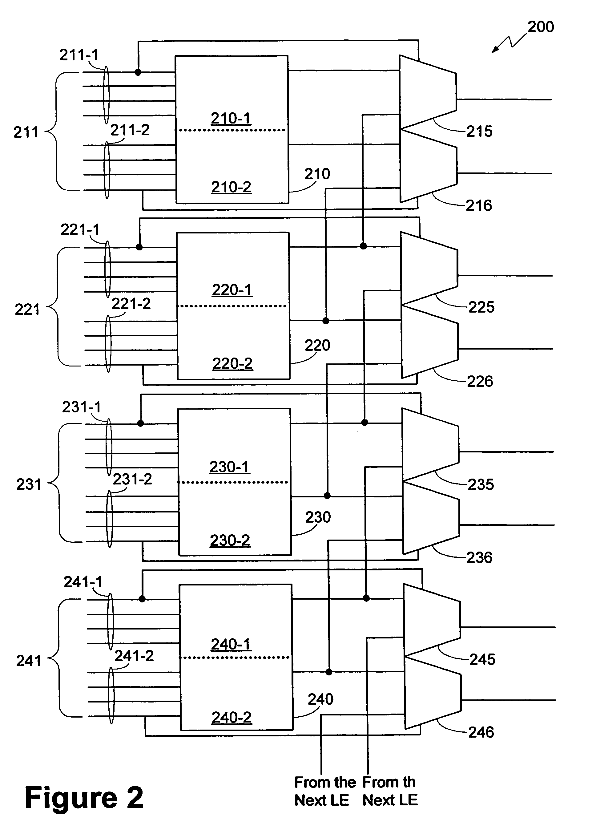
[0009]In one aspect, an embodiment of the present invention provides a logic circuit that provides more efficient multiplexing and barrel shifting than a prior art logic circuit. In one general embodiment, this is accomplished by feeding outputs of LEs in the logic circuit to multiplexers that receive their select signals from input terminals of the LEs in the logic circuit. In one embodiment, each of the LEs provides one output signal. The first LE in the logic circuit provides an output signal to one multiplexer, while each of the remaining LEs in the logic circuit provides an output signal to two multiplexers. In one embodiment, each of the LEs is an eight input LE that includes a six input LUT that functions as a 4:1

Problems solved by technology

While mask programming may have disadvantages relative to some of the field programmable options already listed, it may be useful in certain high volume applications.
Some known methods for implementing one or more of multiplexers, barrel shifters, and crossbars suffer from inefficiencies in the number of LEs required and / or the number of levels of LEs required to perform the desired function.

Method used


Image

  • Logic cell with improved multiplexer, barrel shifter, and crossbarring efficiency
  • Logic cell with improved multiplexer, barrel shifter, and crossbarring efficiency
  • Logic cell with improved multiplexer, barrel shifter, and crossbarring efficiency

Examples


Embodiment Construction

[0016]The following description is presented to enable any person skilled in the art to make and use the invention, and is provided in the context of particular applications and their requirements. Various modifications to the exemplary embodiments will be readily apparent to those skilled in the art, and the generic principles defined herein may be applied to other embodiments and applications without departing from the spirit and scope of the invention. Thus, the present invention is not intended to be limited to the embodiments shown, but is to be accorded the widest scope consistent with the principles and features disclosed herein.

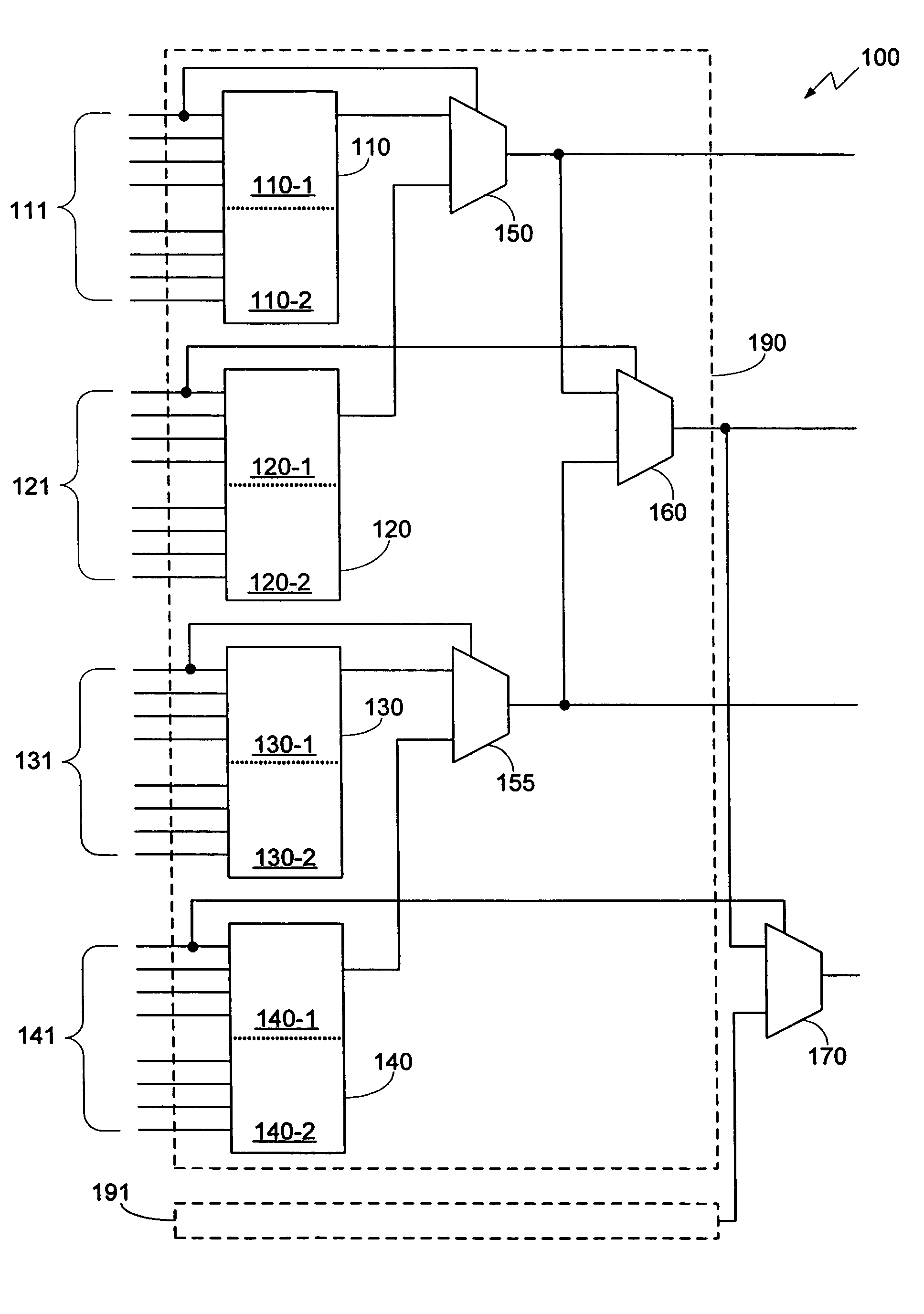
[0017]FIG. 1 is a block diagram of one embodiment of the logic circuit of the present invention. In FIG. 1, logic circuit 100 includes logic blocks 190 and 191 and multiplexer 170. Logic block 190 includes LEs 110, 120, 130, and 140, and multiplexers 150, 155, and 160. LEs 110, 120, 130, and 140 receive signals on LE input terminals 111, 121, 131, and...


PUM


Abstract

Logic circuits that provide improved efficiency are described. In one general embodiment, this is accomplished by feeding outputs of LEs in the logic circuit to multiplexers that receive their select signals from input terminals of the LEs in the logic circuit. In one embodiment, each of the LEs provides one output signal. The first LE in the logic circuit provides an output signal to one multiplexer, while each of the remaining LEs in the logic circuit provides an output signal to two multiplexers. In another embodiment, each of the LEs provides two output signals. The first LE in the logic circuit provides two output signals to one multiplexer, while each of the remaining LEs in the logic circuit provides two output signals to four multiplexers.

Description

BACKGROUND OF THE INVENTION[0001]Programmable logic devices (“PLDs”) (also sometimes referred to as complex PLDs (“CPLDs”), programmable array logic (“PALs”), programmable logic arrays (“PLAs”), field PLAs (“FPLAs”), erasable PLDs (“EPLDs”), electrically erasable PLDs (“EEPLDs”), logic cell arrays (“LCAs”), field programmable gate arrays (“FPGAs”), or by other names), are well-known integrated circuits that provide the advantages of fixed integrated circuits with the flexibility of custom integrated circuits. Such devices typically provide an “off the shelf” device having at least a portion that can be programmed to meet a user's specific needs. Application specific integrated circuits (“ASICs”) have traditionally been fixed integrated circuits. However, it is possible to provide an ASIC that has a portion or portions that are programmable. Thus, it is possible for an integrated circuit device to have qualities of both an ASIC and a PLD. The term PLD as used herein will be considere...

Claims


Application Information

Patent Timeline
IPC IPC(8): H03K19/177
CPCH03K19/1737H03K19/17728
Inventor SCHLEICHER, JAMESPEDERSEN, BRUCEKAPTANOGLU, SINAN
Owner ALTERA CORP
Learn More