Speckle reduction for display system with electromechanical grating

a display system and electromechanical technology, applied in the field of display systems, can solve the problems of reducing the resolution ability of an imaging system, affecting the image quality of the display system, and speckle in the image, so as to reduce the number of components, reduce the level of speckle, and reduce the cost

Inactive Publication Date: 2006-10-10
EASTMAN KODAK CO
View PDF23 Cites 28 Cited by
  • Summary
  • Abstract
  • Description
  • Claims
  • Application Information

AI Technical Summary

Benefits of technology

[0030]It is an advantage of the present invention that it provides a display system using one or more arrays of electromechanical grating devices that generate a reduced level of speckle.
[0031]It is an advantage of the present invention that it provides a full-color display system using arrays of electromechanical grating devices with a reduced number of components, allowing design of a more compact and lower cost apparatus than provided by earlier designs. With a reduced number of components and minimized requirements for adjustment, the apparatus of the present invention provides a robust solution for imaging using electromechanical grating array devices.

Problems solved by technology

However, one problem that is common to systems using electromechanical grating light modulators used with lasers or, more generally, used with highly coherent light sources, is speckle.
A result of perceived interference effects from scattering of the illuminating laser light by surface or volume scatterers of the projection screen, speckle reduces the ability of an imaging system to resolve fine spatial detail and causes levels of noise in an image that can be highly visually annoying.
At worst, without some form of correction, speckle can be sufficiently objectionable to render coherent illumination unsuitable for display purposes.
While conventional methods for speckle reduction may have some applicability to laser projection systems using GEMS and other types of electromechanical grating devices, there are drawbacks to these approaches that constrain image quality and reduce overall contrast as well as adding cost and complexity to projection apparatus.
Speckle remains a problem, therefore, that is only mitigated to some degree using conventional procedures.

Method used


Image

  • Speckle reduction for display system with electromechanical grating
  • Speckle reduction for display system with electromechanical grating
  • Speckle reduction for display system with electromechanical grating

Examples


Embodiment Construction

[0047]The present description is directed in particular to elements forming part of, or cooperating more directly with, apparatus in accordance with the invention. It is to be understood that elements not specifically shown or described may take various forms well known to those skilled in the art.

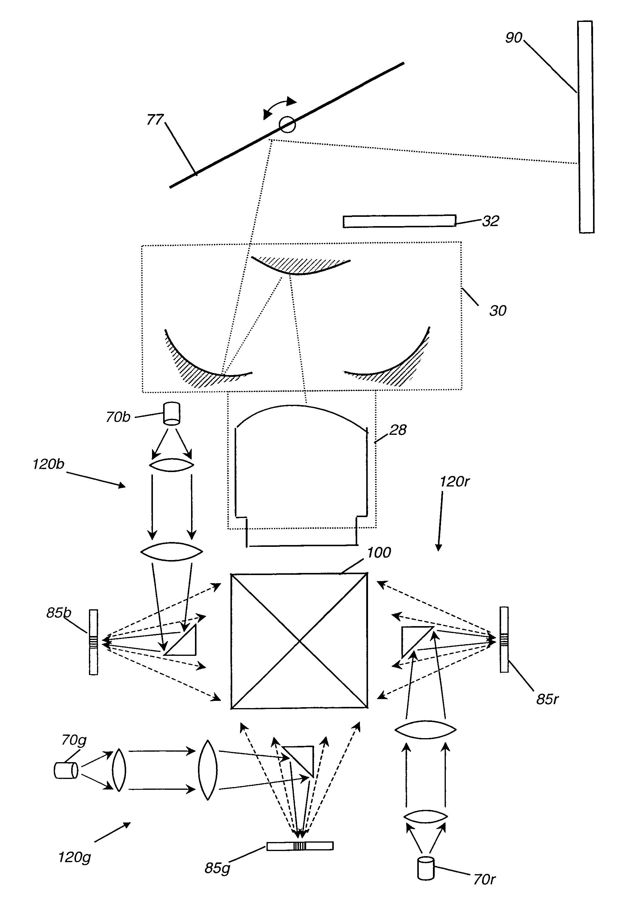
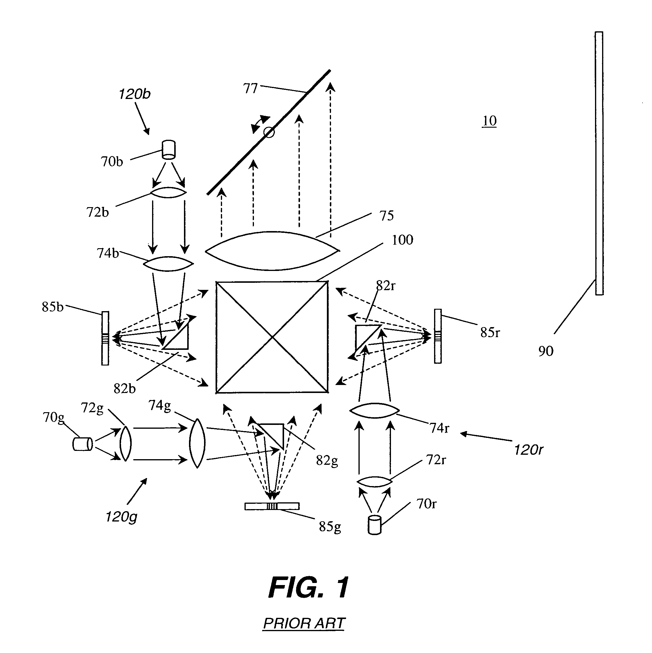
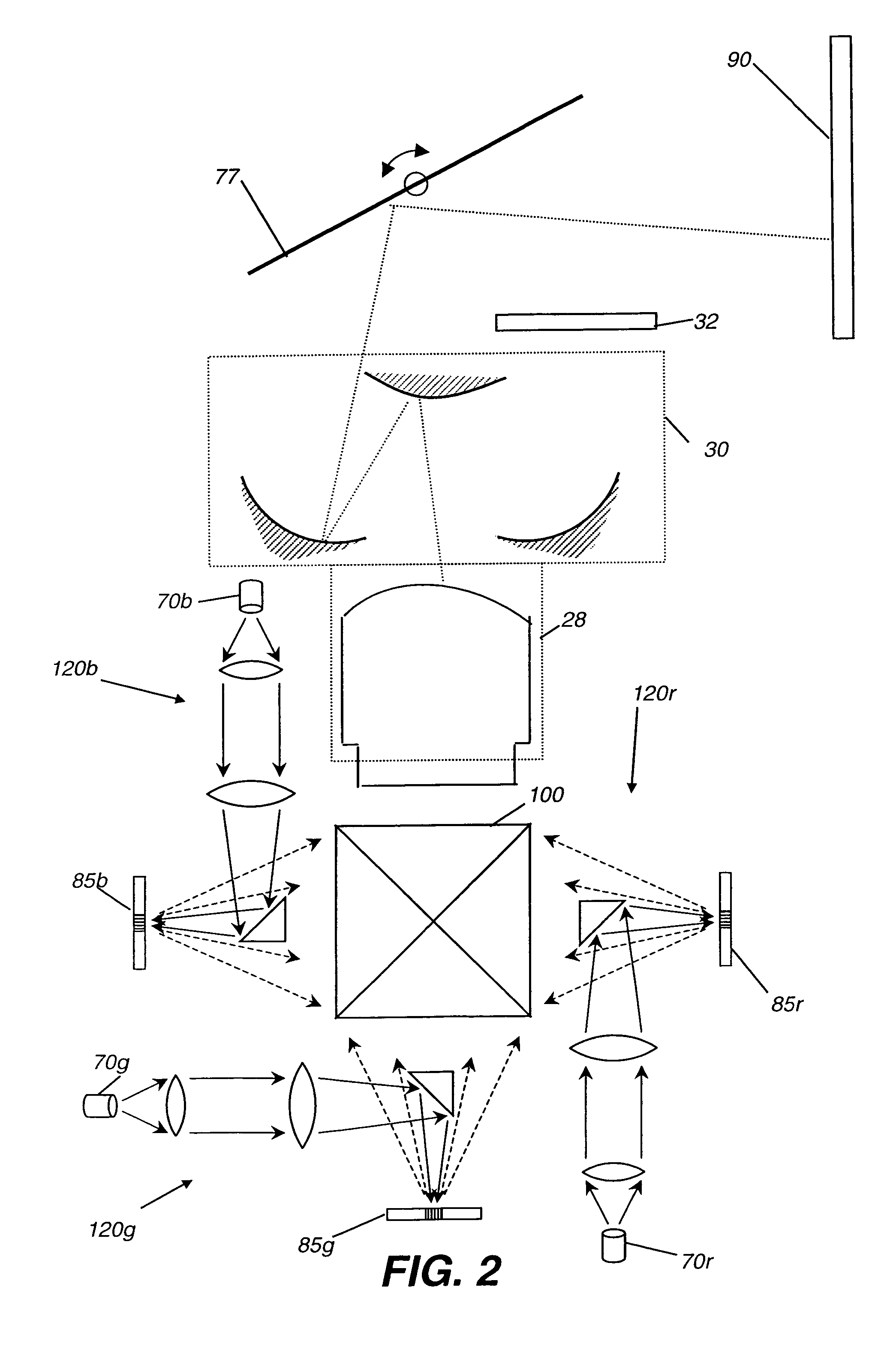
[0048]For the description that follows, components specific to a single color path may be more particularly identified with a letter appended to the part number. Where used, letters correspond to color paths; for example, “r” is appended for red, “b” for blue, “g” for green. Where the description applies to these imaging path components in general, however, the part number may be given without an appended letter.

[0049]The apparatus and method of the present invention take advantage of inherent characteristics of electromechanical grating light modulators for providing a display apparatus having significantly reduced speckle. Due to the high performance of GEMS devices, the adaptation of th...


PUM


Abstract

A display system (10) with reduced speckle has a light source (70) providing an illumination beam and a linear light modulator (85) having at least one linear array of light modulating devices for forming a modulated beam. The modulated beam has a plurality of orders of diffracted light. An obstructing element (82r,82g,82b) blocks a zeroeth order reflected light from the modulated beam. An angle-transforming optical assembly (30) anamorphically conditions the modulated beam. A scanning element (77) scans the modulated beam toward a display surface (90) for forming a two-dimensional image thereon.

Description

FIELD OF THE INVENTION[0001]This invention relates to a display system with a linear array of electromechanical grating devices, scanned in order to generate a two-dimensional image. More particularly, the invention relates to an improved display system using an electromechanical grating device and methods for reducing speckle in the displayed image.BACKGROUND OF THE INVENTION[0002]Spatial Light Modulators (SLMs) based on electromechanical grating devices have been adapted to a wide range of applications, including display, data storage, spectroscopy and printing. Such systems typically use large numbers of individually addressable devices in either a linear array or an area array, with over a million addressable devices desirable for an area modulator array in a high-quality display.[0003]Linear arrays are particularly advantaged over their area array counterparts by virtue of higher resolution, reduced cost, and simplified optics. One advantage of particular interest: linear array...

Claims


Application Information

Patent Timeline
Patent Type & Authority Patents(United States)
IPC IPC(8): G02B26/08G09G3/34
CPCG02B27/1026G02B27/104G02B27/1093G02B27/149G02B27/48H04N9/3132
Inventor KOWARZ, MAREK W.BONILLA, FAROUK H.KRUSCHWITZ, BRIAN E.PHALEN, JAMES G.
Owner EASTMAN KODAK CO
Why Eureka
Try Eureka