Liquid cooling system

a cooling system and liquid cooling technology, applied in the field of liquid cooling systems, can solve the problems of heat generation, other systems operating within the computing system may also generate heat, and add to the heat experienced by the processor

Inactive Publication Date: 2006-10-10
QNX COOLING SYST
View PDF12 Cites 85 Cited by
  • Summary
  • Abstract
  • Description
  • Claims
  • Application Information

AI Technical Summary

Problems solved by technology

The increased circuitry per area of processor as well as the conductive properties of the materials used to build the processors result in the generation of heat.
In addition to the processors, other systems operating within the computing system may also generate heat and add to the heat experienced by the processors.
A range of adverse effects result from the increased heat.
At one end of the spectrum, the processor begins to malfunction from the heat and incorrectly processes information.
For example, when the circuits on a processor are implemented with digital logic devices, the digital logic devices may incorrectly register a logical zero or a logical one.
On the other hand, when the processors become too heated, the processors may experience a physical breakdown in their structure.
These types of physical breakdowns may be irreversible and render the processor and the computing system inoperable and un-repairable.
Many of these conventional approaches are elaborate and costly.
Cold rooms are very costly to build and operate.
The specialized buildings, walls, flooring, air conditioning systems, and the power to run the air conditioning systems all add to the cost of building and operating the cold room.
However, with decreasing profit margins in many industries, operators are not willing to incur the expenses associated with operating a cold room.
In addition, as computing systems are implemented in small companies and in homes, end users are unable and unwilling to incur the cost associated with the cold room, which makes the cold room impractical for this type of user.
However, as processors become more densely populated with circuitry and as the number of processors implemented in a computing system increases, cooling the air within the computing system can no longer dissipate the necessary amount of heat from the processor or the chassis of a computing system.
However, as with the previous techniques, this approach is also limited.
Certainly, larger heat sinks can always be manufactured; however, the size of the heat sink can become so large that heat sinks become infeasible.
However, each of these techniques has limitations.
Refrigeration techniques require substantial additional power, which drains the battery in a computing system.
In addition, condensation and moisture, which is damaging to the electronics in computing systems, typically develops when using the refrigeration techniques.
Heat pipes provide yet another alternative; however, conventional heat pipes have proven to be ineffective in dissipating the large amount of heat generated by a processor.
However, this often results in a processor operating at a level below the level that the processor was marketed to the public or rated.
This also results in slower overall performance of the computing system.
Therefore, although this may protect a processor from structural breakdown or computing breakdown, it reduces the operating performance of the processor and the ultimate performance of the computing system.
While this may be a feasible solution, it is certainly not an optimal solution because processor performance is reduced using this technique.
Therefore, thermal (i.e., heat) issues negate the tremendous amount of research and development expended to advance processor performance.
In addition to the thermal issues, a heat dissipation method and / or apparatus must be deployed in the chassis of a computing system, which has limited space.
Further, as a result of the competitive nature of the electronics industry, the additional cost for any heat dissipation method or apparatus must be very low or incremental.

Method used


Image

  • Liquid cooling system
  • Liquid cooling system
  • Liquid cooling system

Examples


Embodiment Construction

[0066]While the present invention is described herein with reference to illustrative embodiments for particular applications, it should be understood that the invention is not limited thereto. Those having ordinary skill in the art and access to the teachings provided herein will recognize additional modifications, applications, and embodiments within the scope thereof and additional fields in which the present invention would be of significant utility.

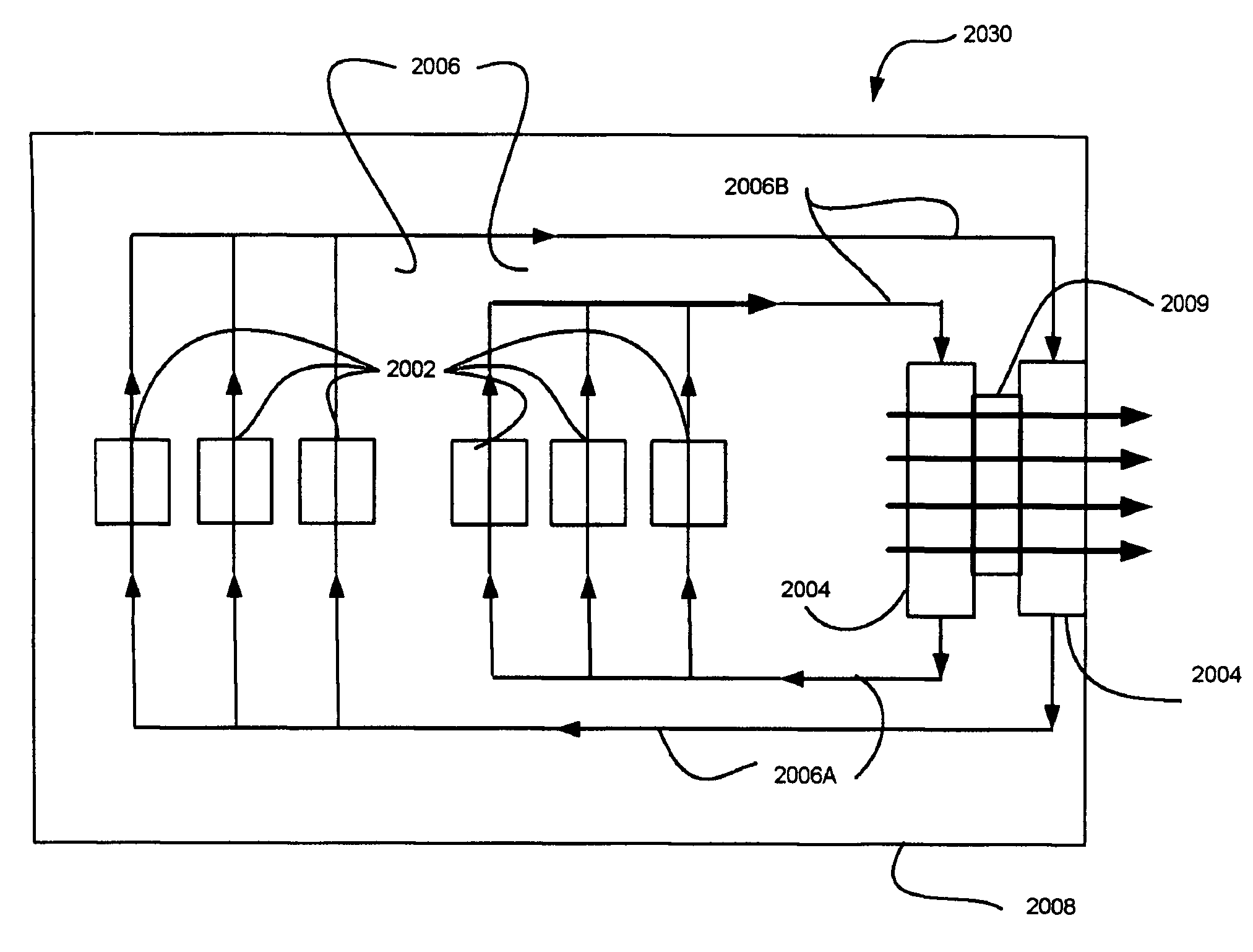
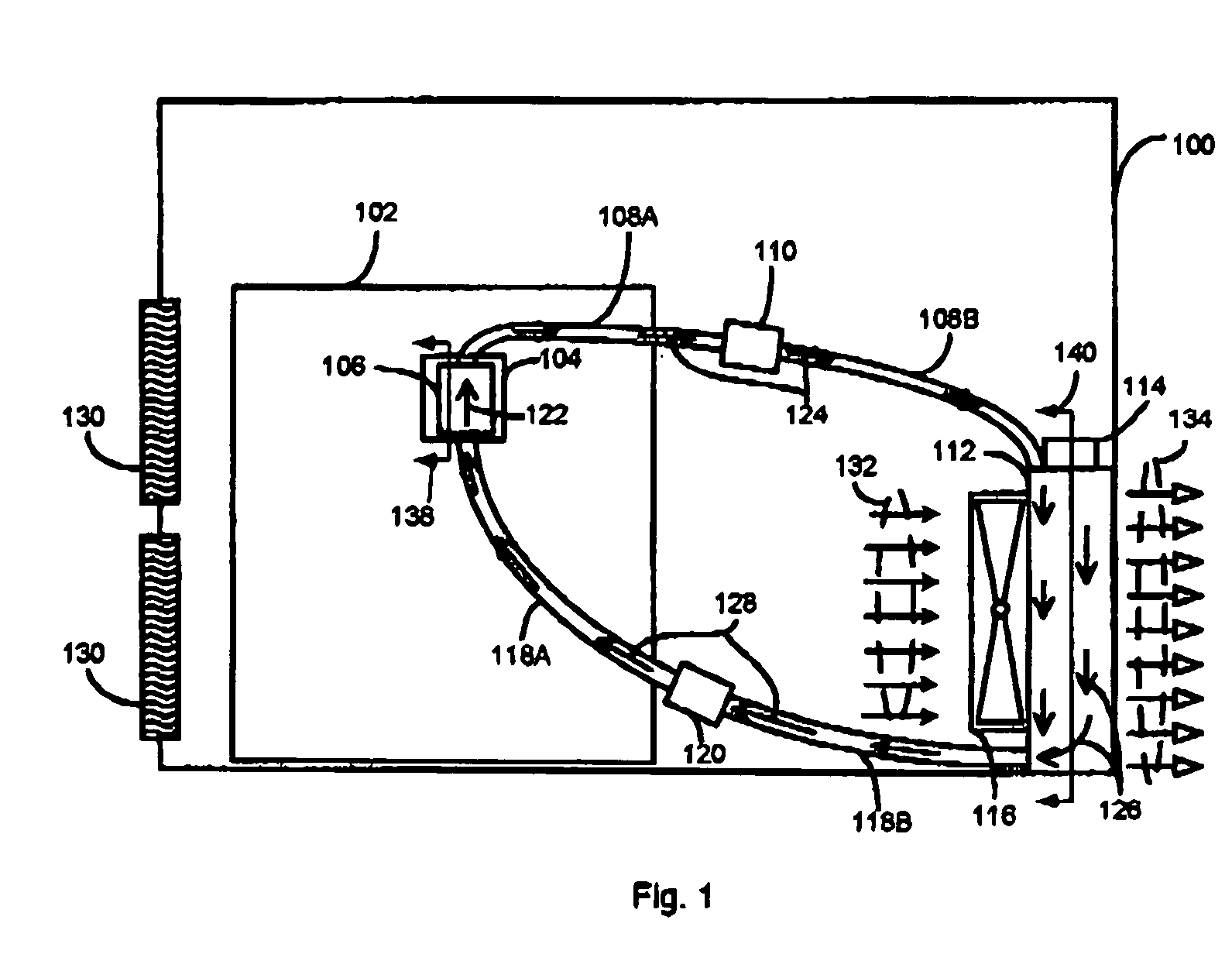
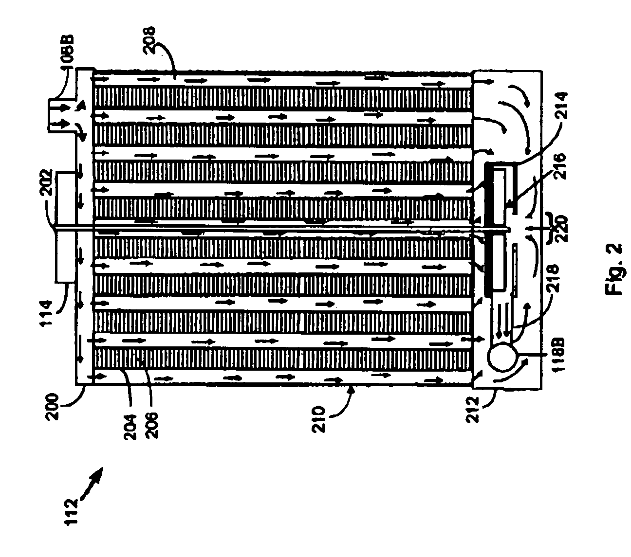
[0067]A variety of liquid cooling systems are presented. In each embodiment of the present invention, a heat transfer system in combination with a heat exchange system is used to dissipate heat from a processor. The various heat transfer systems may be intermixed with the heat exchange systems to create a variety of liquid cooling systems.

[0068]Several heat transfer systems are presented. Each heat transfer system may be used with a variety of heat exchange systems. For example, a heat transfer system is presented; a direct-exposure h...


PUM


Abstract

Liquid cooling systems and apparatus and data processing systems and communication systems with liquid cooling systems are presented. A number of embodiments are presented. In each embodiment a plurality of heat transfer systems capable of engaging a plurality heat generating components and each such heat transfer system adapted to transfer heat from the heat generating components is implemented. Each of the heat transfer systems is in liquid communication with a heat exchange system that receives heated liquid from the heat transfer systems and returns cooled liquid to the heat transfer systems. The liquid communication from / to the heat exchange system and the heat transfer systems is in parallel, in series or a combination of parallel and series. Another embodiment disclosed is for data processing systems and communication systems having rack mounted sub-assemblies which can be inserted into or retracted from a rack or other holding device (and even while the data processing system or the communication system is operating) wherein the liquid communication to the heat transfer systems on a sub-assembly may be switched on or off. Another embodiment is disclosed for the cost effective and noise-muffling deployment of fans in a liquid cooling system having more than one heat exchange system therein.

Description

CROSS REFERENCE TO RELATED APPLICATIONS[0001]The present invention is a continuation-in-part of application Ser. No. 10 / 688,587, filed Oct. 18, 2003, entitled “Liquid Cooling System,” and which is herein incorporated by reference and application Ser. No. 10 / 715,322 filed Nov. 14, 2003 entitled “Liquid Cooling System,” and which is herein incorporated by reference.BACKGROUND OF THE INVENTIONDESCRIPTION OF THE RELATED ART[0002]Processors are at the heart of most computing systems. Whether a computing system is a desktop computer, a laptop computer, a communication system, a television, etc., processors are often the fundamental building block of the system. These processors may be deployed as central processing units, as memories, controllers, etc.[0003]As computing systems advance, the power of the processors driving these computing systems increases. The speed and power of the processors are achieved by using new combinations of materials, such as silicon, germanium, etc., and by po...

Claims


Application Information

Patent Timeline
Patent Type & Authority Patents(United States)
IPC IPC(8): H05K7/20F25B21/02F25D23/12F28D15/00H01L
CPCF28D15/00F28D2021/0029F28D2021/0031
Inventor HAMMAN, BRIAN A.
Owner QNX COOLING SYST
Why Eureka
Try Eureka