Sound reproducing apparatus

a sound reproduction and apparatus technology, applied in the direction of transportation and packaging, fuels, packaging, etc., can solve the problems of inability to appropriately apply the sound reproducing apparatus shown in fig. 12 to recent mobile telephones, and the efficiency of the reproduced sound pressure with respect to the driver is very low compared with that of conventional speakers, and achieves high-quality sound

Active Publication Date: 2006-10-10
SOVEREIGN PEAK VENTURES LLC
View PDF9 Cites 35 Cited by
  • Summary
  • Abstract
  • Description
  • Claims
  • Application Information

AI Technical Summary

Benefits of technology

[0014]Therefore, an object of the present invention is to provide a sound reproducing apparatus capable of reproducing high quality sound while giving the user the sense that the sound is being reproduced from a display means.

Problems solved by technology

Thus, in the sound reproducing apparatus shown in FIG. 11, the efficiency of the reproduced sound pressure with respect to the driver is very low as compared with that of conventional speakers.
The sound reproducing apparatus shown in FIG. 12, on the hand, cannot be appropriately applied to recent mobile telephones in which larger display screens are highly demanded.

Method used


Image

  • Sound reproducing apparatus
  • Sound reproducing apparatus
  • Sound reproducing apparatus

Examples


first embodiment

[0036](First Embodiment)

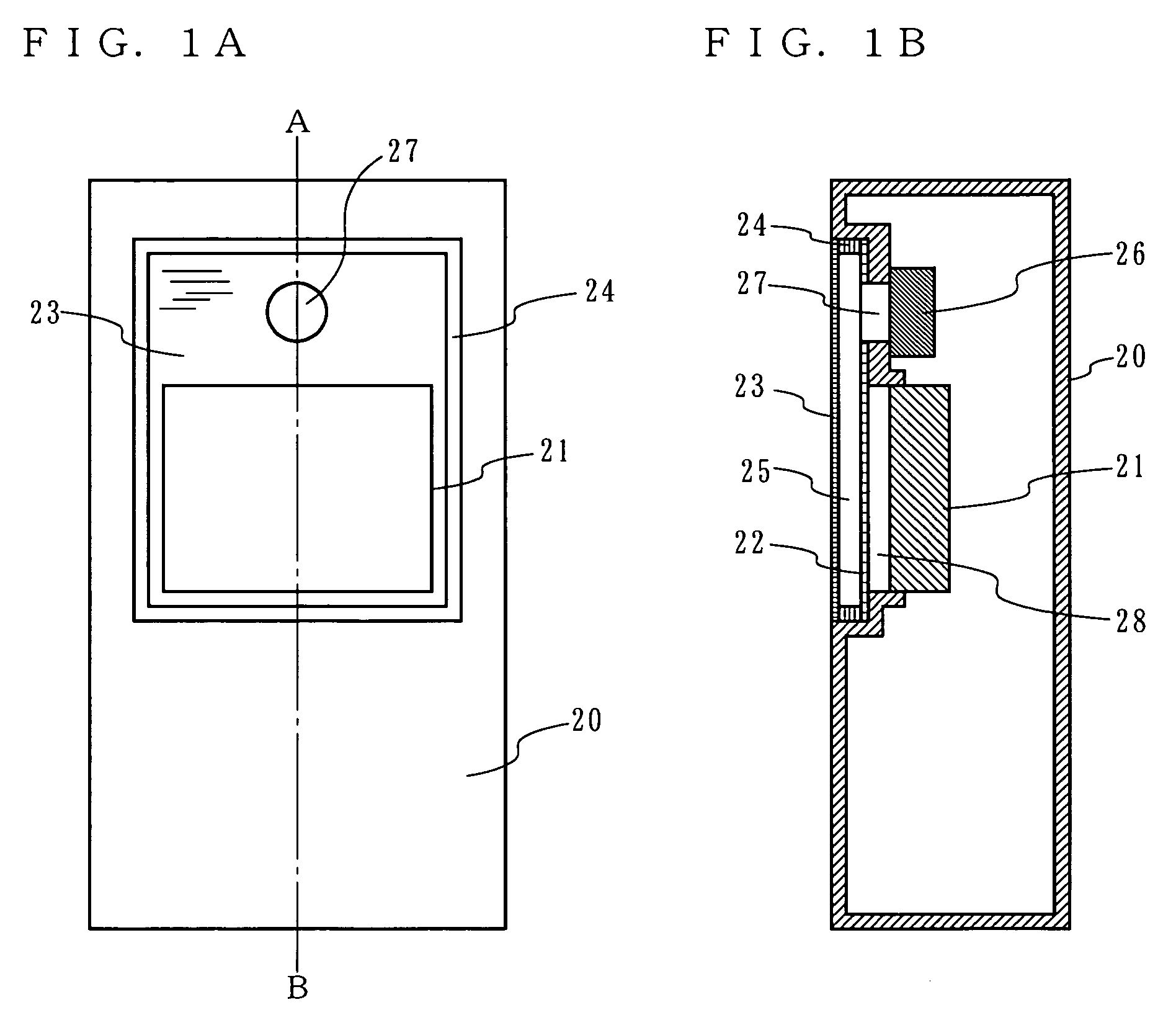
[0037]First, a sound reproducing apparatus according to a first embodiment of the present invention will be described below. FIGS. 1A and 1B are diagrams illustrating a configuration of the sound reproducing apparatus according to the first embodiment. FIG. 1A is a plan view of the sound reproducing apparatus, and FIG. 1B is a cross-sectional view of the sound reproducing apparatus taken along a line A-B of FIG. 1A. The sound reproducing apparatus according to the first embodiment can be implemented as a mobile terminal apparatus such as a mobile telephone or PDA.

[0038]In FIGS. 1A and 1B, the sound reproducing apparatus includes an outer case 20, a display device 21, a board 22, a diaphragm panel 23, a spacer 24, and an electroacoustic transducer 26. The display device 21 may be a liquid crystal display device, for example. The board 22 and the diaphragm panel 23 are composed of materials which transmit visible light. The board 22 is composed of glass or acry...

second embodiment

[0050](Second Embodiment)

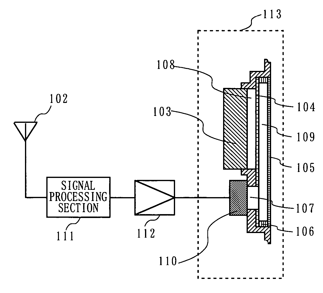
[0051]With reference to FIGS. 3 to 5, a sound reproducing apparatus according to a second embodiment will be described below. The second embodiment describes a sound reproducing apparatus which is implemented as a mobile telephone. FIG. 3 is a plane view illustrating a mobile telephone according to the second embodiment which is partially cut out. FIG. 4 is a block diagram illustrating the mobile telephone according to the second embodiment.

[0052]In FIGS. 3 and 4, a mobile telephone 100 includes an outer case 101, an antenna 102, a display device 103, a board 104, a diaphragm panel 105, a spacer 106, a sound hole 107, an electroacoustic transducer 110, a signal processing section 111, and a signal amplification section 112. In FIG. 3, the outer case 101 contains electrical circuits and the like of the mobile telephone 100. The antenna 102 is mounted to the outer case 101. In FIG. 3, the diaphragm panel 105 is partially cut out. In FIG. 4, the signal processi...

third embodiment

[0058](Third Embodiment)

[0059]A sound reproducing apparatus according to a third embodiment will be described below with reference to the drawings. The sound reproducing apparatus according to the third embodiment is also implemented as a mobile terminal apparatus, as with the first embodiment. The sound reproducing apparatus according to the third embodiment has two electroacoustic transducers.

[0060]FIGS. 7A and 7B are diagrams illustrating the sound reproducing apparatus according to the third embodiment. FIG. 7A is a plane view illustrating the sound reproducing apparatus, and FIG. 7B is a cross-sectional view of the sound reproducing apparatus taken along a line C-D of FIG. 7A. In FIGS. 7A and 7B, the sound reproducing apparatus includes an outer case 130, a display device 131, a board 132, a diaphragm panel 134, a spacer 140, a first electroacoustic transducer 136, and a second electroacoustic transducer 138. In the third embodiment, a first sound hole 137 and a second sound ho...


PUM


Abstract

A sound reproducing apparatus includes a display unit, a board 22, a diaphragm panel 23, and an electroacoustic transducer 26. The display unit displays an image on a display surface. The board 22 is composed of a material which transmits visible light and arranged such that a first space is provided between the display surface of the display unit and the board 22. The diaphragm panel 23 is composed of a material which transmits visible light and arranged on the opposite side of the board 22 from the display unit such that a second space is provided between the board 22 and the diaphragm panel 23. The electroacoustic transducer 26 emits sound into the second space.

Description

BACKGROUND OF THE INVENTION[0001]1. Field of the Invention[0002]The present invention relates to a sound reproducing apparatus, and more particularly to a sound reproducing apparatus having a display means and being capable of acoustically driving a transparent diaphragm panel.[0003]2. Description of the Background Art[0004]Conventionally, there has been devised a sound reproducing apparatus for reproducing sound from a display screen. For example, there exists a sound reproducing apparatus which causes a transparent diaphragm panel provided in front of a display screen to vibrate to emit sound. This sound reproducing apparatus will be described below with reference to FIG. 11.[0005]FIG. 11 is an external perspective view of a television set having a conventional sound reproducing apparatus. In FIG. 11, the television set includes a cabinet 1, a cathode ray tube 2, a front panel 3, a driver 4, and sound slits 5. The front panel 3 is mounted in front of the cathode ray tube 2. The fr...

Claims


Application Information

Patent Timeline
Patent Type & Authority Patents(United States)
IPC IPC(8): H04R25/00H04B1/38H04M1/03H04R1/02
CPCH04M1/03H04R1/025H04R2499/15H04R2499/11B65D71/00C10L5/36
Inventor SAIKI, SHUJIUSUKI, SAWAKO
Owner SOVEREIGN PEAK VENTURES LLC
Why Eureka
Try Eureka