Airborne vehicle for firefighting

a firefighting and airborne technology, applied in direction controllers, instruments, weapons, etc., can solve the problems of other objects to burn, periphery of firefighting, and inability to distribute extinguishant uniformly

Inactive Publication Date: 2006-10-17
BODENSEEWERK GERATETECHNIK GMBH
View PDF28 Cites 32 Cited by
  • Summary
  • Abstract
  • Description
  • Claims
  • Application Information

AI Technical Summary

Benefits of technology

[0006]The present invention is based on the technical problem of providing an airborne vehicle which allows efficient firefighting with an area effect that is greater than that in the prior art.

Problems solved by technology

This has the disadvantage that the extinguishant is not distributed uniformly if the environmental topology is poor.
In the worst case, the fire is fanned out, spread by a certain amount of the extinguishant striking an object whose position is thus changed, and thus itself now causes other objects to burn.
This results in the periphery of the fire being fought.
Efficient firefighting is impossible.
However, what is already in flames is generally subject to the destructive effect of the fire until it is completely destroyed, and can no longer be rescued.

Method used


Image

  • Airborne vehicle for firefighting
  • Airborne vehicle for firefighting
  • Airborne vehicle for firefighting

Examples


Embodiment Construction

[0044]Identical parts are in this case annotated by the same reference symbols.

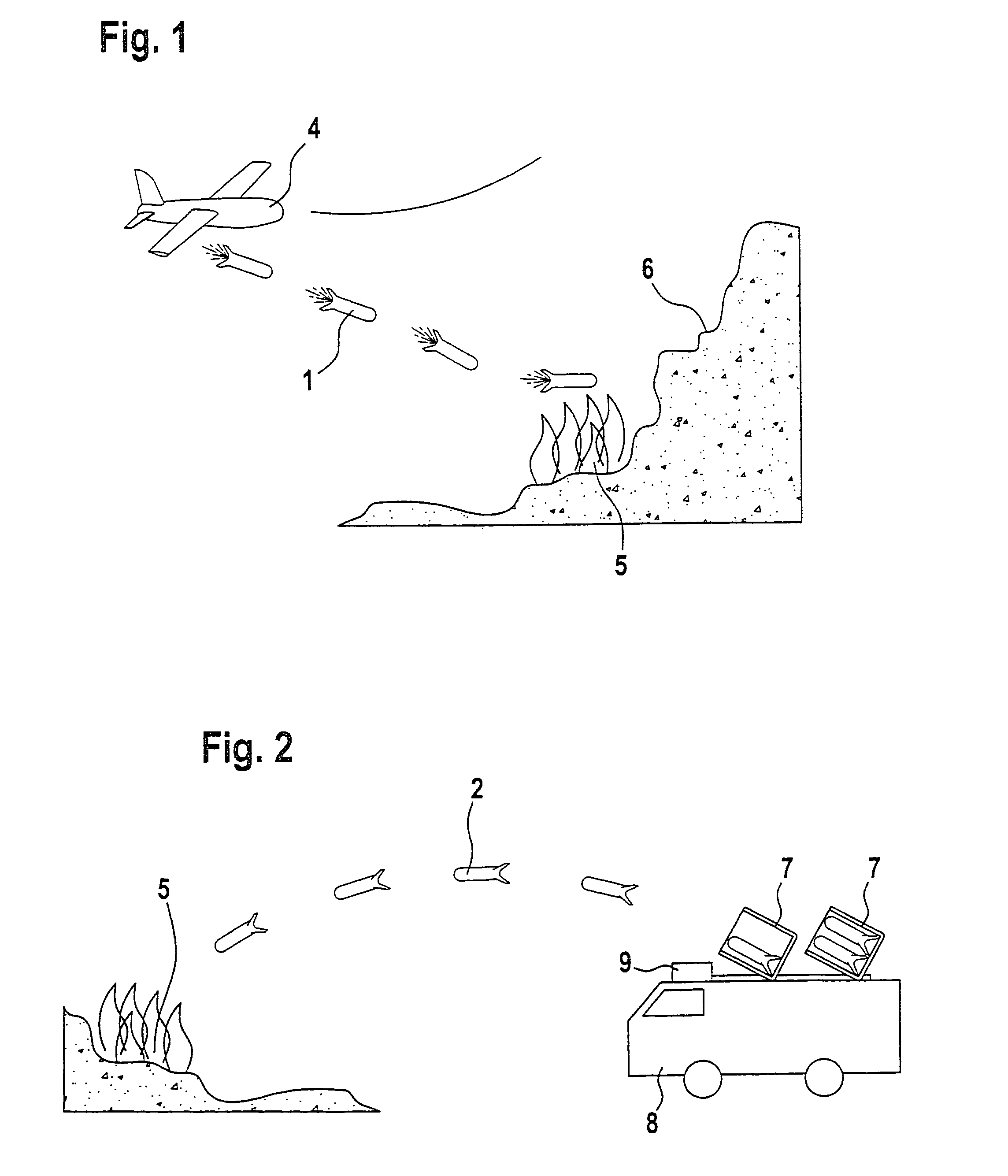
[0045]FIG. 1 shows the firing of an airborne vehicle 1 from an aircraft 4. The airborne vehicle 1 has its own propulsion system, as can be seen from the exhaust gas jet that is illustrated. After firing, the aircraft 4 remains at a relatively long safety distance from the fire 5, since the airborne vehicle 1 is able, by virtue of its propulsion system, to travel over relatively long distances itself. Although the fire 5 is located at the edge of a mountain range 6, this allows firefighting capabilities.

[0046]The aircraft 4 can turn away safely before it reaches the mountain range 6.

[0047]FIG. 2 shows an airborne vehicle 2 without its own propulsion system being launched from a launch device 7. The launch device 7 is fitted to an extinguishing vehicle 8 and is aimed at the fire 5 by means of a sensor system 9 that is connected to the launch device 7, such that the flightpath of the airborne vehicle 2 ends ...


PUM


Abstract

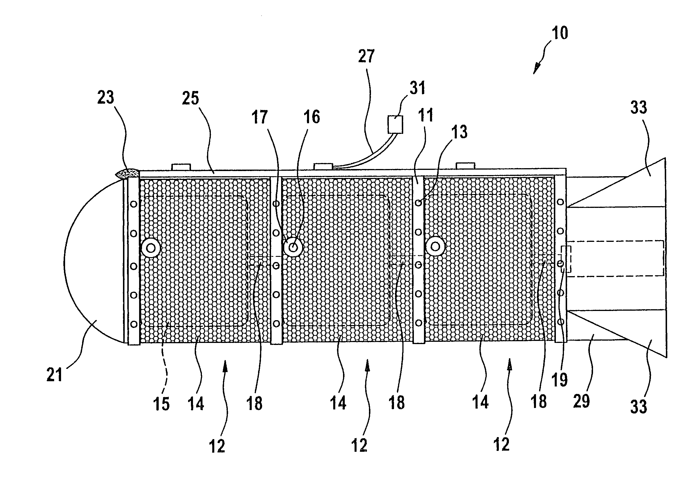
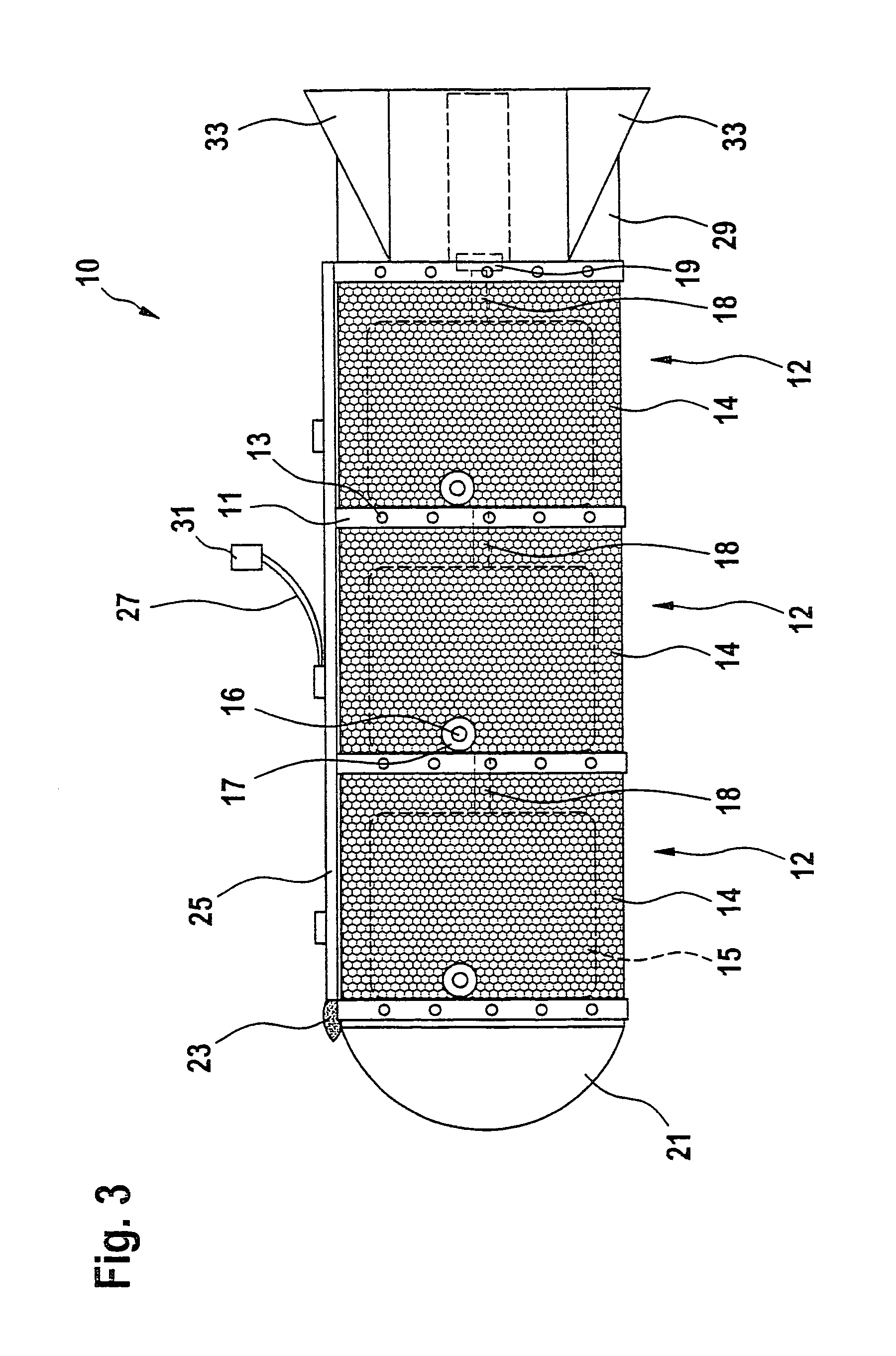
An airborne vehicle (1, 2, 10) which is equipped with an extinguishant container (12) for mist extinguishing is specified for efficient firefighting. A detonator (18) which is located on the extinguishant container (12) can be detonated via a fuze (19). The detonator (18) is attached to the airborne vehicle (1, 2, 10) such that, on firing the extinguishant which is contained in the extinguishant container (12) produces an extinguishant mist.

Description

BACKGROUND OF THE INVENTION[0001]1. Field of the Invention[0002]The invention relates to an airborne vehicle for firefighting, which possesses an extinguishant container, a detonator, and a fuze.[0003]2. Discussion of the Prior Art[0004]U.S. Pat. No. 3,980,139 and FR 1 473 621 disclose a so-called fire extinguishing bomb as an airborne vehicle of the type mentioned initially for firefighting, which comprises a cylindrical gas or plastic container for holding an extinguisher, and an inner container which is arranged concentrically in it, for holding a detonator. The detonator is in this case fired by the external influence of the heat produced by a fire. This has the disadvantage that the extinguishant is not distributed uniformly if the environmental topology is poor. While the flames are extinguished at some points, the fire has time at other points to propagate even more strongly and, possibly, to cause areas that have already been extinguished to burn once again. In the worst cas...

Claims


Application Information

Patent Timeline
Patent Type & Authority Patents(United States)
IPC IPC(8): A62C35/02A62C25/00A62C27/00A62C29/00A62C37/00A62C3/02A62C19/00
CPCA62C3/025
Inventor SETZER, UWE
Owner BODENSEEWERK GERATETECHNIK GMBH
Why Eureka
Try Eureka