Carriage for a power washer wand

a technology for power washers and wands, which is applied in the direction of watering devices, cleaning using liquids, brushes, etc., can solve the problems of inability to easily, reliably and easily manually manipulate devices, and the assembly of such devices is obviously time-consuming and costly, so as to increase the ease of positioning the nozzle, the effect of maximum cleaning and shortest amount of time without damag

Inactive Publication Date: 2006-10-17
DALEY HOWARD
View PDF22 Cites 14 Cited by
  • Summary
  • Abstract
  • Description
  • Claims
  • Application Information

AI Technical Summary

Benefits of technology

[0011]With the foregoing in mind, the present invention provides a carriage for supporting a power washer wand which eliminates the disadvantages of the devices exemplified by the prior art described earlier and listed herein through the construction of a polymeric / copolymeric molded one-piece homogeneous carriage which is defined by a platform, wheel axle supports on an underside of the platform and a wand support projecting upwardly from a forwardly converging nose of the platform. The converging and narrow nature of the nose facilitates accessability of the carriage and the associated high velocity water spray to difficult-to-access areas which are to be cleaned. Additionally, the power washer wand is adjustably supported by the wand support but, more importantly, the wand support is inclined rearwardly at two angles, one between a lower wand support portion of the platform and the other between the lower wand support portion and an upward wand portion to achieve the most efficient spray angle relative to the surface which is to be cleaned to achieve maximum cleaning in the shortest amount of time without damage (gouging wood of decks, for example). A single wheel is also provided immediately beneath the nose of the platform which further augments the ease of positioning the nozzle with respect to hard-to-access areas (corners, etc.).

Problems solved by technology

For example, most of the devices are very large, cumbersome, constructed from a multiplicity of parts, are very expensive to manufacture, assembly thereof is obviously time-consuming and costly, and from a functional standpoint, the devices cannot be readily, reliably and easily manually manipulated to direct high velocity spray to precise and difficult-to-access areas.

Method used


Image

  • Carriage for a power washer wand
  • Carriage for a power washer wand
  • Carriage for a power washer wand

Examples


Embodiment Construction

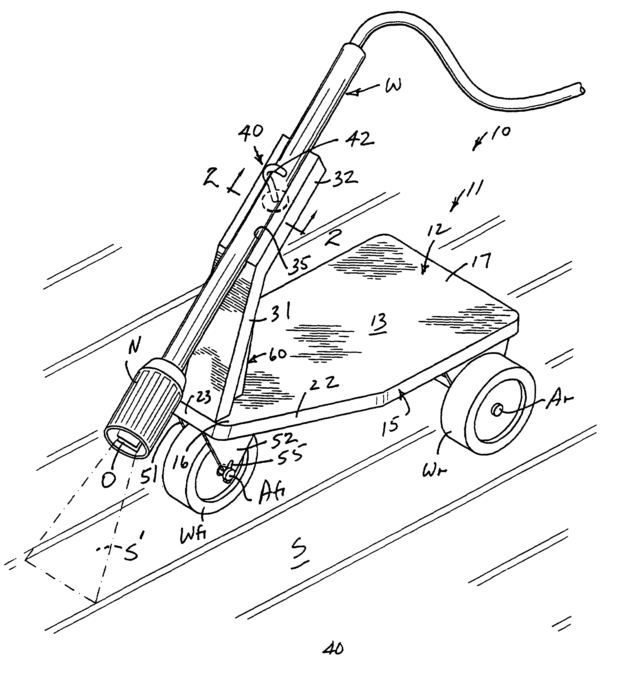
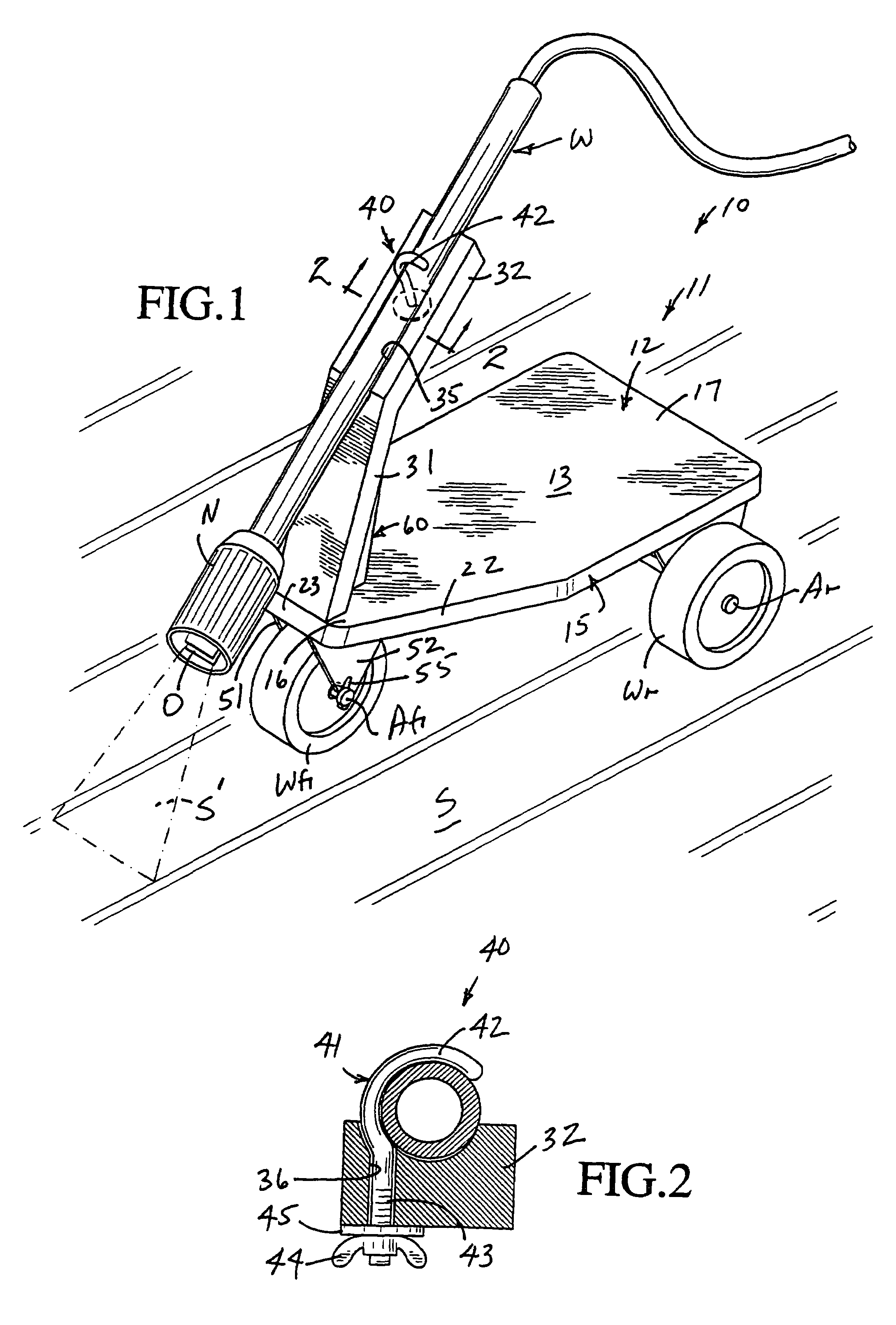
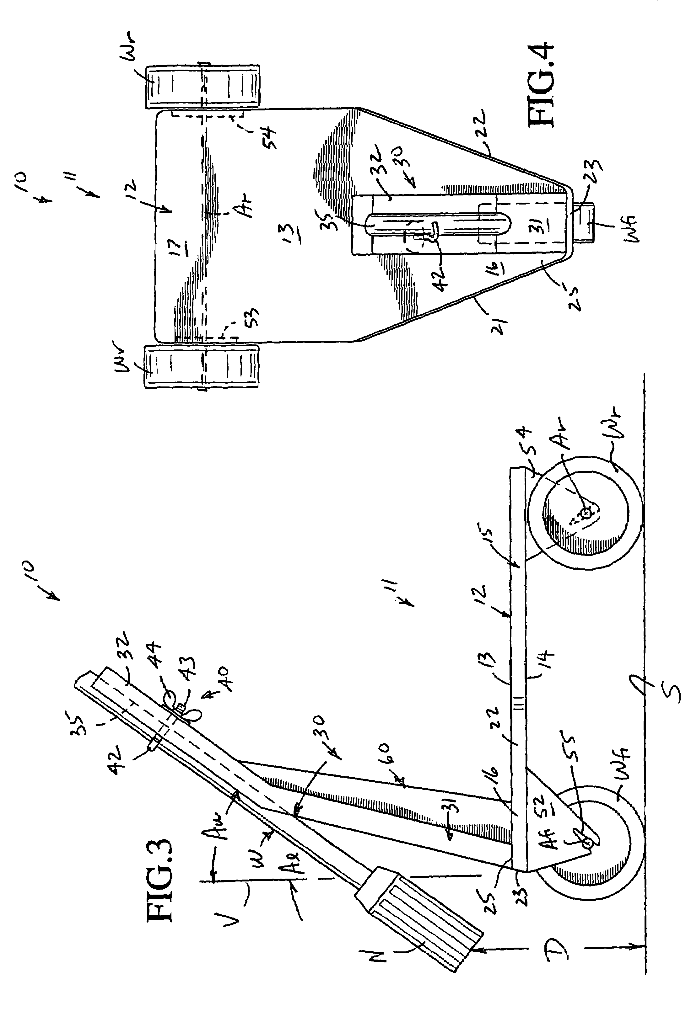
[0017]A carriage 10 particularly adapted for supporting a power washer wand W and an associated high pressure nozzle N thereof a predetermined, though adjustable, distance from a surface S which is to be cleaned by a high velocity water spray S′ exiting a discharge orifice O of the nozzle N is fully illustrated in FIGS. 1, 3 and 4 of the drawings.

[0018]The carriage 10 includes a one-piece carriage body 11 molded from substantially homogeneous, high strength, synthetic polymeric / copolymeric plastic material, such as structural foam polypropylene injection molded in a die draw aluminum mold.

[0019]The carriage body 11 includes a platform 12 defined by an upper surface 13, a lower surface 14 and a peripheral surface or peripheral edge 15 between the upper and lower surfaces 13, 14, respectively. The platform 12 further includes a front platform end portion 16 and a rear platform portion 17 with the front platform portion 16 being defined between opposite front side edge portions 21, 22 ...


PUM


Abstract

A carriage designed for supporting a power washer wand and its nozzle a predetermined, though adjustable, distance from a surface which is to be cleaned by high velocity water exiting a discharge orifice of the nozzle. The carriage is defined by a one-piece body molded from substantially high strength synthetic polymeric / copolymeric plastic material. The carriage body includes a platform having a converging front end nose upwardly from which projects a wand support having a channel in which a power washer wand is located and adjustably clamped. The platform includes two wheels at a rear end thereof and a single wheel beneath the front end nose.

Description

BACKGROUND OF THE INVENTION[0001]Heretofore a variety of different wheeled carriages or platforms have been provided for movably and / or adjustably supporting devices which perform disparate functions.[0002]One such device is the line marking device of U.S. Pat. No. 4,892,251 granted on Jan. 9, 1990 to Harrison Bresnen. An airless paint spray mechanism is adjustably attached to a four-wheeled carrier to deliver a trapezoidal paint spray to the surface of a road or pavement to mark stripes of varying widths.[0003]U.S. Pat. No. 5,265,805 granted on Nov. 30, 1993 to Steven M. Artenian discloses an apparatus for cleaning parking lots, sidewalks and the like utilizing hot pressurized water which sprays downwardly within a manifold similar to a lawnmower chassis. A group of spray nozzles rotate in a plane parallel to the surface which is to be cleaned, and the chassis includes two rear wheels and a single forward wheel for easing movement during cleaning.[0004]U.S. Pat. No. 5,898,970 grant...

Claims


Application Information

Patent Timeline
Patent Type & Authority Patents(United States)
IPC IPC(8): B05B3/00B05B3/18B08B3/00A62C31/24B05B15/06
CPCB05B13/005B05B15/62
Inventor DALEY, HOWARD
Owner DALEY HOWARD
Why Eureka
Try Eureka