Armrest structure for vehicle

a technology for armrests and vehicles, applied in the direction of roofs, doors, pedestrian/occupant safety arrangements, etc., can solve the problems of poor appearance from the inside of the vehicle compartment, insufficient load absorption, and the armrest cannot provide sufficient rigidity with respect to a load occurring in a vertical direction, etc., to achieve the effect of sufficient supporting rigidity of the recess member

Active Publication Date: 2006-10-17
MAZDA MOTOR CORP
View PDF9 Cites 68 Cited by
  • Summary
  • Abstract
  • Description
  • Claims
  • Application Information

AI Technical Summary

Benefits of technology

[0012]The present invention has been devised in view of the above-described problems, and an object of the present invention is to provide an armrest structure for a vehicle that can maintain a proper impact-absorption function during the vehicle side collision, and thus can provide both sufficient resistance for a load applied to the armrest in a vertical direction and the proper impact-absorption function.

Problems solved by technology

The above-described conventional structure, however, had a problem of a poor appearance from the inside of a vehicle compartment.
Accordingly, there was a problem that a sufficient load absorption could not be obtained.
In addition, since the armrest is divided into two parts by respective slant faces 688a, 687a in its normal state as shown in FIG. 24, there was a problem that the armrest could not provide sufficient rigidity with respect to a load occurring in a vertical direction.
The above-described conventional structure, however, had the same problem of poor appearance from the inside of the vehicle compartment as the above.
Additionally, since at least the horizontal potion 696 remains in the same shape as that in its normal state as illustrated in FIG. 26 at the time of its impact load absorption during the side vehicle collision, there was a problem that a sufficient load absorption could not be obtained.

Method used


Image

  • Armrest structure for vehicle
  • Armrest structure for vehicle
  • Armrest structure for vehicle

Examples


embodiment 1

[0100]An armrest structure for a vehicle according to a first embodiment will be described referring to FIGS. 4, 5 and 6.

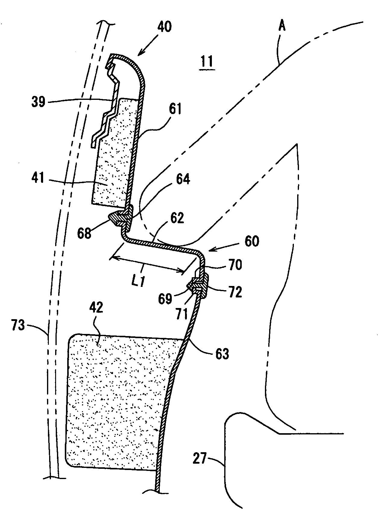
[0101]The above-described door trim 40 is provided with an armrest 60 formed integrally with the door trim 40 which protrudes and extends toward the passenger A from an inside wall (the door inner panel 39 of the front door 22 in the embodiment) of the vehicle compartment 11.

[0102]The armrest 60 comprises a trim body portion 61 (upper portion of the door trim 40) which covers the inside wall of the vehicle compartment, an armrest face portion 62 for armrest of the passenger A which extends in a substantially horizontal direction from the trim body portion 61 toward the inside of the vehicle compartment 11 by a specified length L1 (a necessary length for passengers to put their arms), and a support face portion 63 which extends continuously from the armrest face portion 62 downward.

[0103]Herein, as illustrated in FIGS. 5 and 6, there are provided plural openings 64...

embodiment 2

[0133]An armrest structure for a vehicle according to a second embodiment will be described referring to FIGS. 10, 11 and 12.

[0134]The above-described door trim 140 is provided with an armrest 160 formed integrally with the door trim 140 which protrudes and extends toward the passenger A from an inside wall (the door inner panel 39 of the front door 22 in the embodiment) of the vehicle compartment 11.

[0135]The armrest 160 comprises a trim body portion 161 (upper portion of the door trim 140) which covers the inside wall of the vehicle compartment, an armrest face portion 162 for armrest of the passenger A which extends in the substantially horizontal direction from the trim body portion 161 toward the inside of the vehicle compartment 11 by the specified length L1 (a necessary length for passengers to put their arms), and a support face portion 163 which extends continuously from the armrest face portion 162 downward.

[0136]There are provided first openings 164 . . . 164 as a weak po...

embodiment 3

[0154]FIG. 14 illustrates a third embodiment of the present invention. Herein, the thickness t2 (see FIG. 14) of the door trim 240 of the present embodiment is set to be thicker than the thickness t1 (see FIG. 10) of the door trim 140 of the previous embodiment (t2>t1). Further, there are provided notch portions 272, 273, 274 at the bottom face of the connecting piece 265 remaining between the first openings 164 . . . 164 (see FIG. 11), which are located at portions corresponding to the opening edge (end portions in the vehicle width direction) of the first openings 164 . . . 164 and at the middle portion of the connecting piece 265 in the vehicle width direction. Other structures of the present embodiment illustrated in FIG. 14 are the same as those of the previous embodiment.

[0155]In the present embodiment, the load resistance of the armrest in use in the vertical direction can be further improved by the door trim 240 with the thickness of t2. Further, the rigidity with respect to...


PUM


Abstract

A structure of an armrest protruding and extending toward a passenger from an inside wall of a vehicle compartment, comprises a trim body portion covering the inside wall, an armrest face portion extending in a substantially horizontal direction from the trim body portion toward an inside, and a support face portion extending continuously from the armrest face portion downward. There is provided a weak portion (deformation promoting portion) between the trim body portion and the armrest face portion to promote deformation with respect to a lateral load. Further, there is provided a garnish covering the weak portion from the vehicle compartment. Accordingly, both sufficient resistance of the armrest in use for the load applied in the vertical direction and proper impact-absorption function of the armrest during the vehicle side collision can be obtained.

Description

BACKGROUND OF THE INVENTION[0001]The present invention relates to an armrest structure for a vehicle in which an armrest is disposed so as to protrude and extend toward a passenger from an inside wall of a vehicle compartment.[0002]Generally, the armrest of the vehicle protrudes from the inside wall of the vehicle compartment toward an inside of the vehicle compartment, and it has sufficient rigidity to sustain a load applied thereto in a vertical direction because a passenger put its armrest on the armrest.[0003]It has been required that such armrest has its structure that would not give an improper impact to the passenger during a side collision of the vehicle. Thus, conventionally, some structures to absorb such impact of the armrest have been invented.[0004]In one of conventional armrest structures for the vehicle illustrated in FIG. 24 (see, for example, Japanese Laid-Open Patent Publication No. 2002-46520), a boss 684 for attaching an armrest lower 683 is fixed to a door trim ...

Claims


Application Information

Patent Timeline
Patent Type & Authority Patents(United States)
IPC IPC(8): B60R21/04B60N2/75B60J5/04
CPCB60J5/0451B60J5/0461B60N2/464B60N2/4653B60N2/466B60N2/4666B60N2/4235B60N2/783B60N2/78B60N2/777B60N2/77
Inventor HIROTANI, YASUNARIKUNIHIRO, SHINGOSEKIMOTO, KEIJI
Owner MAZDA MOTOR CORP
Why Eureka
Try Eureka