Device for a ball-and-socket joint type connection of two members

a technology of ball and socket joint and joint, which is applied in the direction of ligaments, prostheses, osteosynthesis devices, etc., can solve the problem that the connection mechanism must have a large overall height, and achieve the effect of small overall height of the connection mechanism

Inactive Publication Date: 2006-10-17
SYNTHES USA
View PDF13 Cites 124 Cited by
  • Summary
  • Abstract
  • Description
  • Claims
  • Application Information

AI Technical Summary

Benefits of technology

[0013]because the joint head is fixed in the cavity by the clamping means, the front end of which can be brought into contact with a depression at the joint head, the latter can be configured lower, as a result of which the device has smaller dimensions.
[0015]by configuring the front end of the clamping means as a point, which is concentric with the central axis, a punctiform contact between the front end and the depression can be achieved;
[0020]Preferably, the joint head of the bone-fixation means may be constructed rigidly, so that no expansion of the joint head is possible when the device is locked.
[0027]Alternatively, the transverse channel may open toward the side of the device, i.e., a side-loading pedicle screw. The side-loading pedicle screw may also include a covering cap, which may be pushed over the connecting member parallel to the central axis. The covering cap may include a tab formed parallel to the central axis, the tab enabling the channel opening to be closed when the mounting means is tightened, thereby clamping the longitudinal member inside the channel between the wall of the channel and the tab. In this embodiment, with respect to the central axis, the channel preferably is offset from the channel opening so that it becomes possible that the clamping screw may be screwed into the connecting member adjacent to the channel, so that, in comparison to the previous embodiments, the clamping screw can be screwed into the connecting member below the channel, thereby reducing the overall height of the connecting member even more.

Problems solved by technology

One disadvantage of the connecting mechanism in these known devices is that the connecting mechanism must have a generally large, overall height.
One disadvantage with this device is that, because the convex, front end of the clamping means is pressed into the conical cavity at the screw head of the bone screw, there is a wedging effect which creates a levering force, which aligns the bone screw parallel with the central axis of the connecting mechanism.

Method used


Image

  • Device for a ball-and-socket joint type connection of two members
  • Device for a ball-and-socket joint type connection of two members
  • Device for a ball-and-socket joint type connection of two members

Examples


Embodiment Construction

[0044]For the purposes of promoting an understanding of the principles of the invention, reference will now be made to an exemplary, non-limiting embodiment illustrated in the figures and specific language will be used to describe the same. It will nevertheless be understood that no limitation of the scope of the invention is hereby intended, such alterations and further modifications, and such further applications of the principles of the invention as illustrated herein being contemplated as would normally occur to one skilled in the art to which the invention relates.

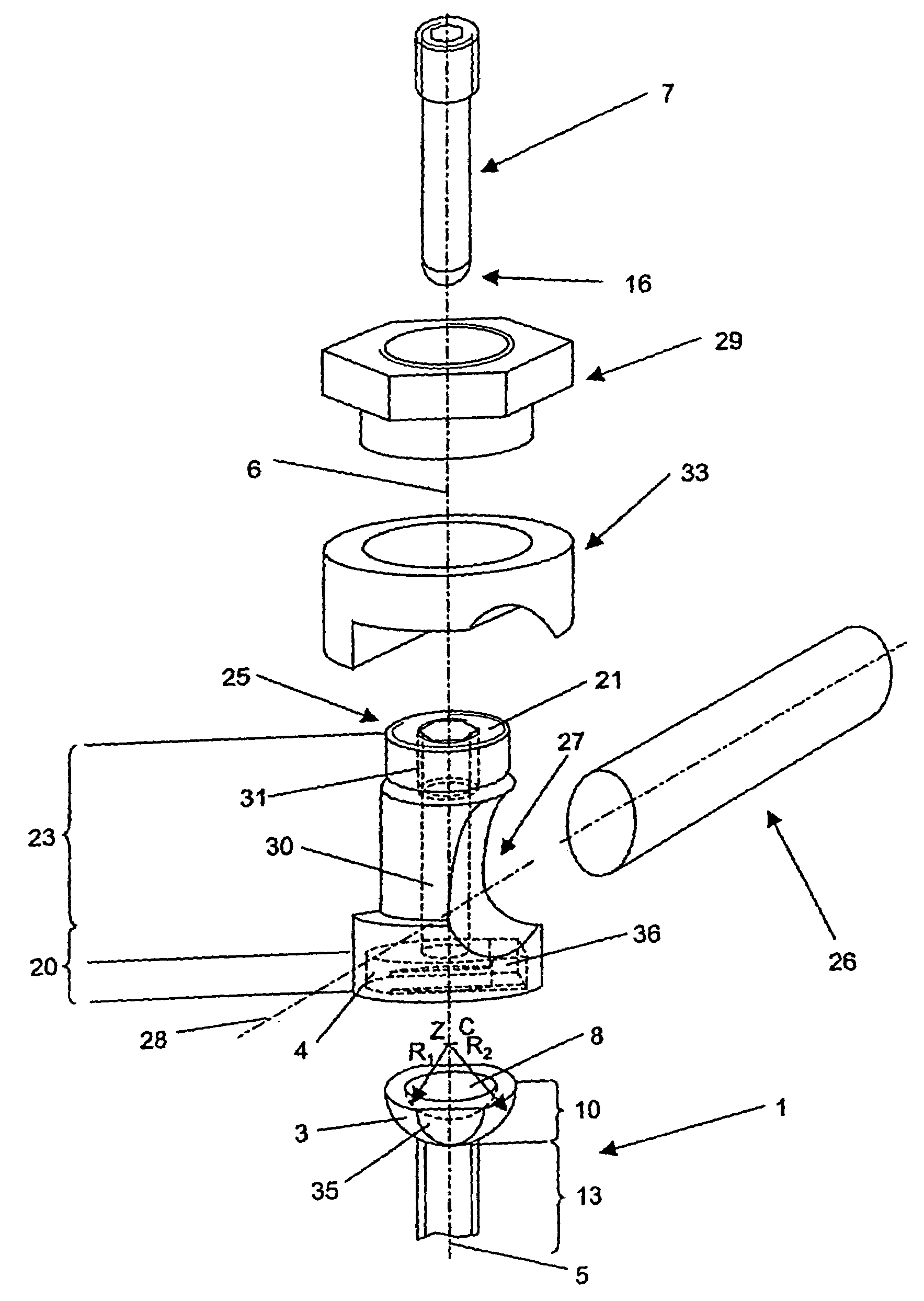
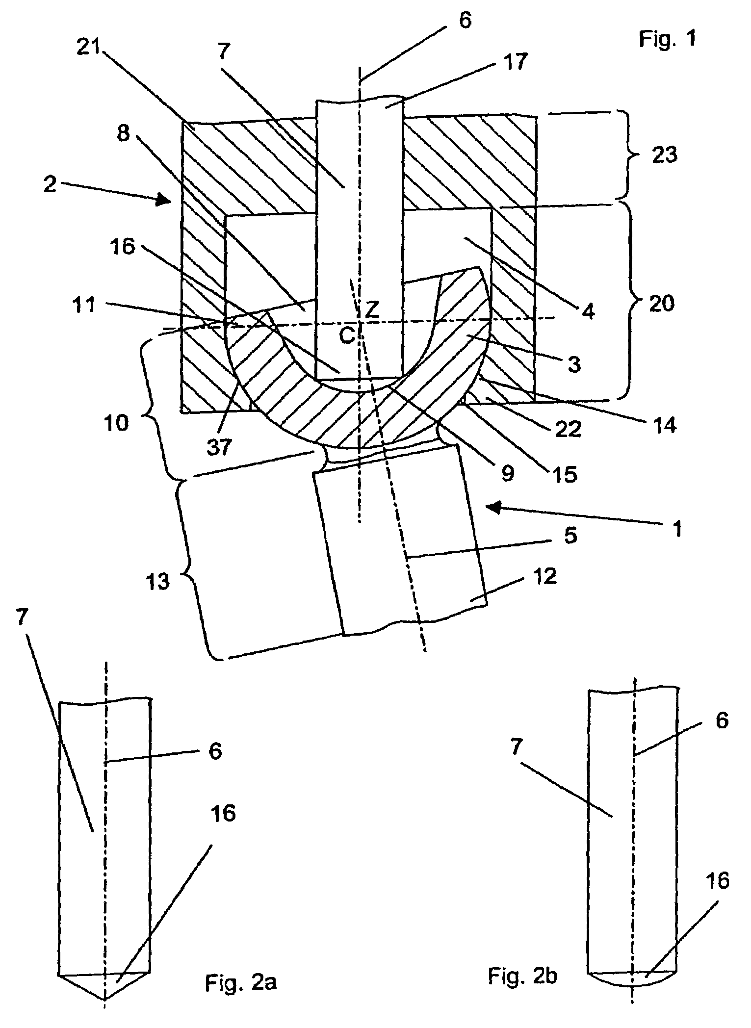
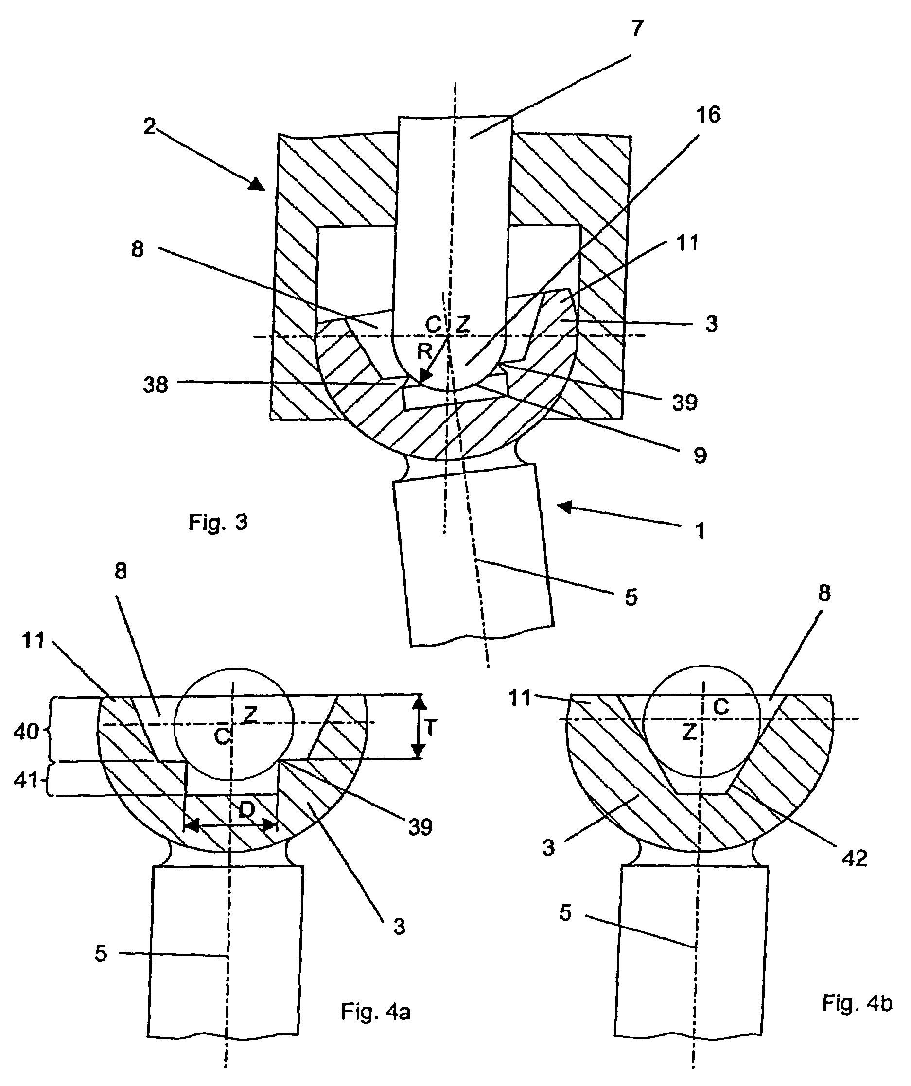
[0045]As shown in FIG. 1, the device includes a first member 1 and a second member 2, wherein the second member 2 includes a cavity 4 and clamping means 7 while the first member 1 has a central axis 5, an upper end 11, and a lower end 12. The upper end 11 of the first member 1 may include a first joint segment 10, which may be constructed as a spherically shaped joint head 3, the center of which, preferably lies on th...


PUM


Abstract

A device for a ball-and-socket-type connection of two members includes a first member having a head and a second member having a cavity that receives the head. The cross-sectional surface of the cavity is tapered at the lower end of the second member as a result of a constriction. The head and / or cavity is configured spherically with a center of articulation (Z). The ball-and-socket-type connection between the two members can be detachably fixed by a clamping element that can be connected to the second member. The head has a recess in which the front end of the clamping element can rest. The recess and / or the front end has an at least partially spherical surface with a centre (C). In the clamped position of the device, the center of articulation (Z) and the centre (C) are identical.

Description

[0001]This application is a continuation of pending application PCT / CH01 / 00744 filed Dec. 31, 2001.FIELD OF THE INVENTION[0002]The invention relates to a device for the ball-and-socket joint type connection of two parts.BACKGROUND OF THE INVENTION[0003]A stabilization device that interconnects the bone-fixation means, such as pedicle screws, with a longitudinal member, such as a longitudinal spinal rod, extending along at least a portion of a patient's spinal column, is used, for example, for the internal stabilization of the spinal column. In order to securely stabilize the spinal column, it should be possible to connect the bone-fixation means, on the one hand, firmly with the vertebrae and, on the other, with the longitudinal member. Preferably, the head of the bone fixation means and the longitudinal member are connected by a connecting mechanism, which permits the longitudinal member to be fixed with respect to the bone-fixation means at a variety of different angles. Moreover,...

Claims


Application Information

Patent Timeline
Patent Type & Authority Patents(United States)
IPC IPC(8): A61F2/44A61B17/70
CPCA61B17/7037A61B17/7041A61B17/7032Y10T403/32196Y10T403/32311Y10T403/32639Y10T403/32204Y10T403/7188
Inventor SCHLAPFER, FRIDOLINDEFRANCESCHI, RENZO
Owner SYNTHES USA
Why Eureka
Try Eureka