

Tooth positioning appliances and systems
a technology for teeth and positioning appliances, applied in the field of orthodontics, can solve problems such as unfavorable temperature control, and achieve the effect of convenient implanting and suitable us
Inactive Publication Date: 2006-10-17
ALIGN TECH
View PDF103 Cites 166 Cited by
- Summary
- Abstract
- Description
- Claims
- Application Information
AI Technical Summary
Benefits of technology
[0013]Use of such removal mechanisms is advantageous in a number of respects. Environmental changes can be easily implanted by a practitioner or patient. For example, the practitioner or patient can wash the mouth with an appropriately heated, pH-modified, ionic strength controlled, or other solution which can induce the desired change in the removal mechanism. While the use of mechanically, electrically, or optically triggered removal mechanisms may require additional equipment, such mechanisms can also be very simple and suitable for use by the patient as well as the practitioner. In all cases, the removal mechanisms can usually be made reversible, i.e. the appliance can be “switchable” between attached configurations where the appliance will remain in place on the teeth and a release configuration where the appliance can be removed form the teeth. This is a particular advantage since is allows the appliance to be temporarily “reconfigured” and removed for any purpose and then repositioned over the teeth to continue the treatment.
Problems solved by technology
For example, temperature would not be a good choice unless it is intended that the appliance be removed when eating or drinking hot foods and drinks.
Method used
View moreImage
Smart ImageViewing Examples

Examples
example 1
[0044]
LayerMaterialThicknessTemp. Phase1Polycarbonate 5 milsHi Temp.2Polyvinyl chloride(PVC)10 milsLow Temp.3PVC10 milsLow Temp.4PVC10 milsLow Temp.5PVC10 milsLow Temp.6Polycarbonate 5 milsHi Temp
example 2
[0045]
LayerMaterialThicknessTemp. Phase1Polycarbonate10 milsHi Temp.2PVC10 milsLow Temp.3PVC10 milsLow Temp.4Polycarbonate10 milsHi Temp.
example 3
[0046]
LayerMaterialThicknessTemp. Phase1PMMA 5 milsHi Temp.2Polyethelyne (PE)10 milsLow Temp.3PE10 milsLow Temp.4PE10 milsLow Temp.5PE10 milsLow Temp.6PMMA 5 milsHi Temp.
Login to View More PUM
 Abstract
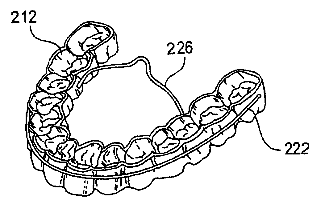
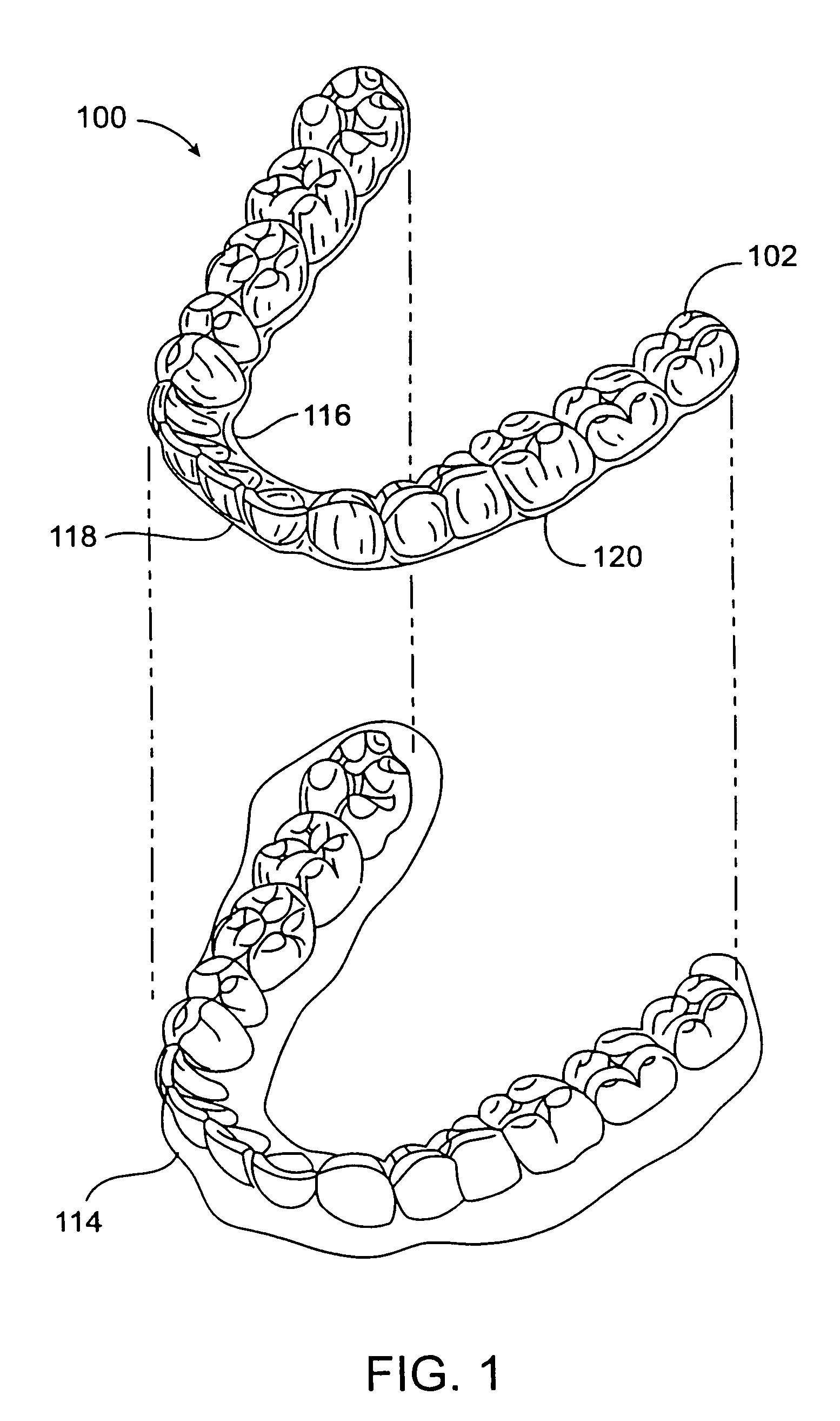
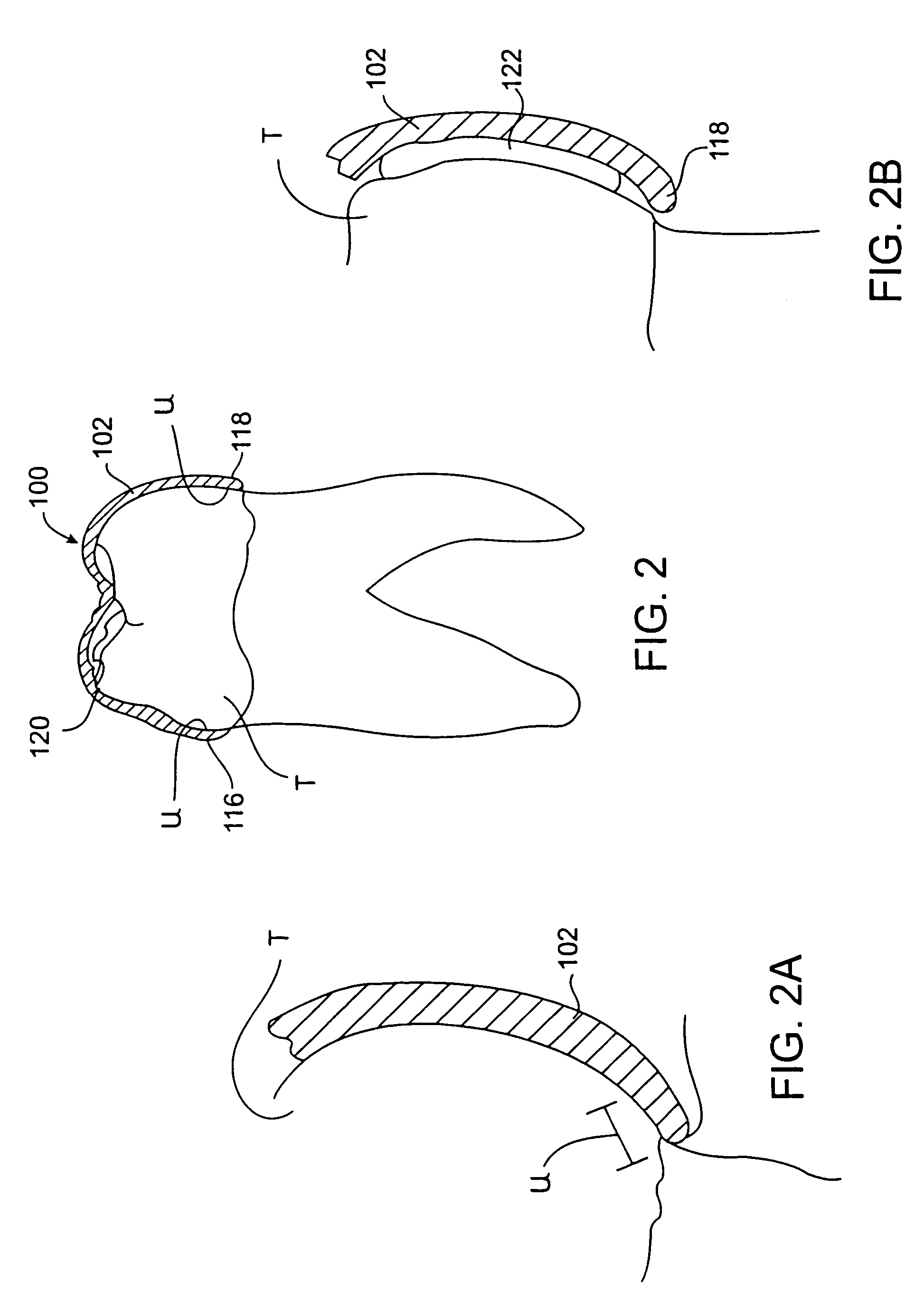
An improved dental appliance system, and methods for using and fabricating the improved appliance, including a polymeric overlay or shell having a teeth-receiving cavity formed therein and a wire mounted on or embedded in the polymeric shell. The dental appliance having the necessary stiffness or strength to firmly secure the appliance on the teeth and provide controlled forces required for repositioning the teeth, until such time as removal of the appliance is desired. The appliance may be configured for use with a removal mechanisim. The removal mechanism undergoes a state change stimulated by an environmental stimulus or environmental switch.
Description
CROSS-REFERENCES TO RELATED APPLICATIONS[0001]The present application is a continuation-in-part of U.S. patent application Ser. No. 10 / 262,516, filed Sep. 30, 2002 (now U.S. Pat. No. 6,705,861, issued Mar. 16, 2004), which was a continuation of U.S. patent application Ser. No. 10 / 099,187, filed Mar. 13, 2002 (now U.S. Pat. No. 6,485,298, issued Nov. 26, 2002), which was a continuation of U.S. patent application Ser. No. 09 / 757,385, filed Jan. 8, 2001 (now U.S. Pat. No. 6,390,812, issued May 21, 2002), which was a continuation of U.S. patent application Ser. No. 09 / 250,962, filed Feb. 16, 1999 (now U.S. Pat. No. 6,183,248, issued Feb. 6, 2001), which claimed the benefit and priority of U.S. Provisional Patent Application No. 60 / 110,189, filed Nov. 30, 1998. This application is also a continuation-in-part of U.S. patent application Ser. No. 10 / 139,153, filed on May 2, 2002, which was a continuation-in-part of PCT Application No. PCT / US01 / 13280, filed Apr. 24, 2001, which was a continu...
Claims
Login to View More Application Information
Patent Timeline
 Patent Type & AuthorityPatents(United States)
IPC IPC(8): A61C7/00A61C7/08A61C7/36A61C13/00
CPCA61C7/00A61C7/08A61C7/36A61C13/0004
InventorCHISHTI, MUHAMMADPHAN, LOC X.MILLER, ROSS J.KUO, ERIC
OwnerALIGN TECH