
Light-generating apparatus control system

a control system and light-generating apparatus technology, applied in the direction of electric variable regulation, process and machine control, instruments, etc., can solve the problems of bulb losing 20% of its light output, power source performance degrading, and bulb intensity quickly starting to dim to unacceptable levels, so as to improve the flexibility of operation for users

Inactive Publication Date: 2006-10-17
IVERS KEVIN THOMAS
View PDF13 Cites 16 Cited by
  • Summary
  • Abstract
  • Description
  • Claims
  • Application Information

AI Technical Summary

Benefits of technology

[0012]The present invention relates to a system for controlling the operation of a light-generating apparatus. The invention is designed to address drawbacks present in control devices of conventional design, such as described in the section above, and to provide enhanced flexibility of operation for the user.

Problems solved by technology

A problem typically encountered with light-generating apparatus is that shortly after replenishment of the power source, the performance of the power source starts to degrade, and the intensity of the light quickly begins to dim to unacceptable levels.
Indeed, as Weber further points out, only a 7% drop in battery voltage causes the bulb to lose 20% of its light output.
The filler gas used in the bulb also affects performance.
The problem is even more severe with “Krypton” gas-filled bulbs that, as Weber points out, drain the battery relatively more rapidly.
Accordingly, designers and operators have faced a trade-off between diminished lighting ability, with attendant frustration and risks, and premature replacement or replenishment of the batteries, with attendant inconvenience, inefficiency, and costs.

Method used


Image

  • Light-generating apparatus control system
  • Light-generating apparatus control system
  • Light-generating apparatus control system

Examples


Embodiment Construction

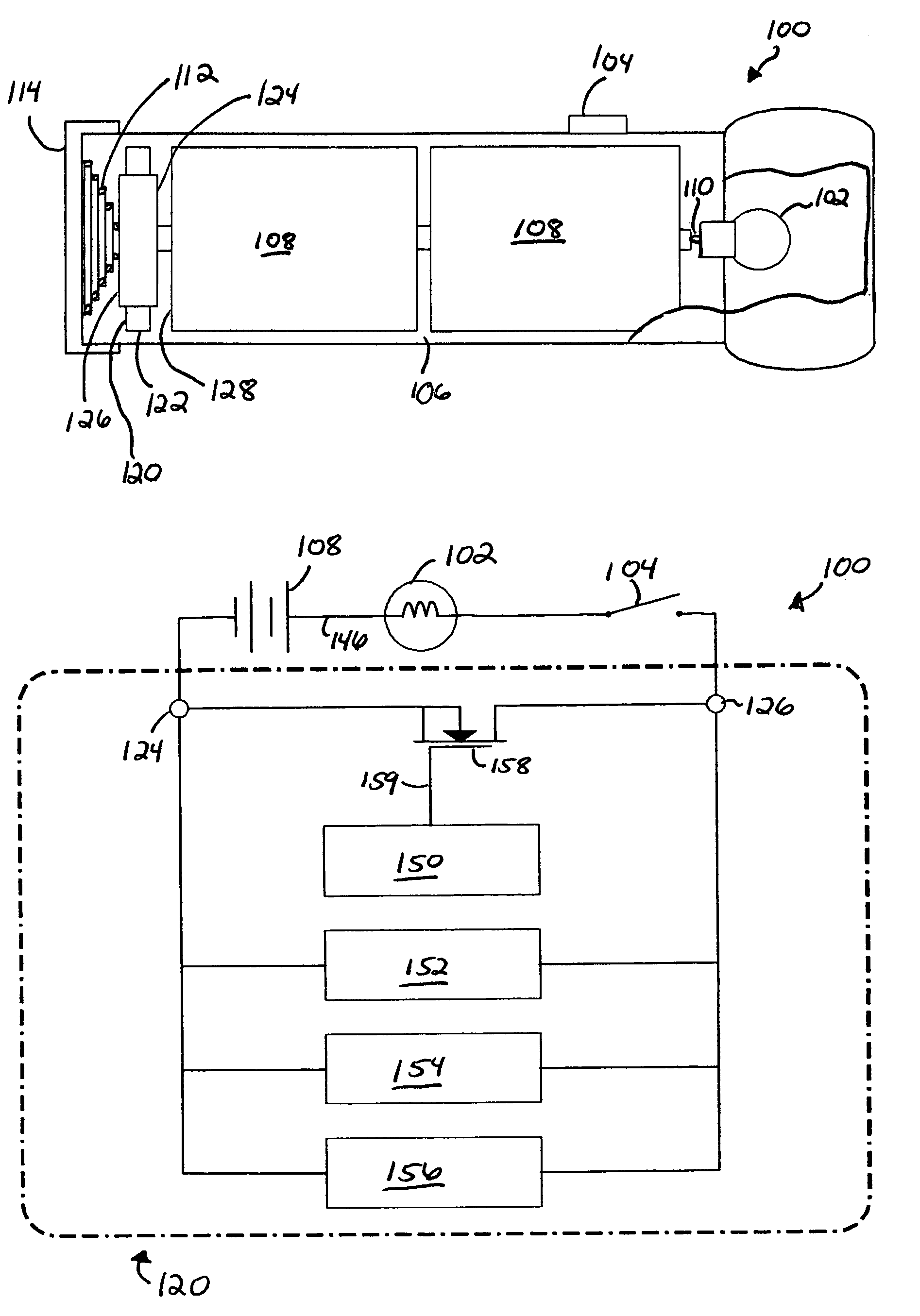
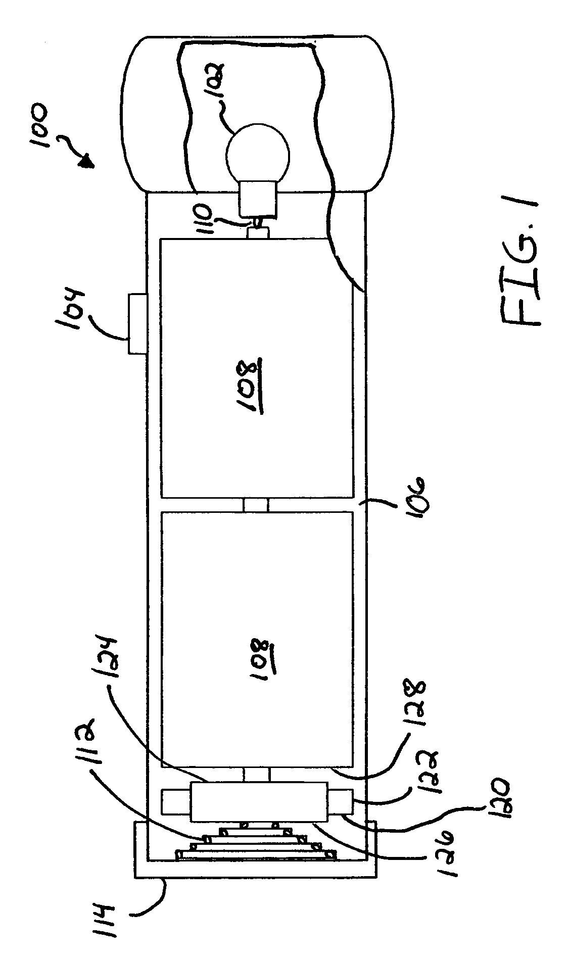
[0033]The present invention relates to a device and method for controlling a light-generating apparatus. In one preferred embodiment of the invention shown in FIG. 1, for example, the light-generating apparatus 100 is an ordinary flashlight. The flashlight includes a light or lamp 102, such as a xenon-filled bulb, and a switch 104 that can be manually actuated by the user. Here the switch is actuatable (shown as slidable) between an OFF and an ON position. Although the switch is shown as slidable, some other form of switch, such a depressible push-button, key-type, or multiple-position switch, could be provided. The flashlight shown includes a battery compartment 106 for holding a removable pair of dry-cell batteries (e.g., AAA, AA, C, or D sized) that act as the power source 108 for the flashlight. These batteries are normally biased against the contact point 110 of the lamp by a coiled spring 112 that defines a lower contact point and is fitted to a screw-off base 114. Absent the ...


PUM


Abstract

A control system for a light-generating apparatus can include a control cyclically operating a switching element in series with the circuit including the apparatus's power source and light. Upon actuation of the apparatus's switch within a specified switching interval, the control shifts to a drift mode causing the circuit to automatically pass through consecutive excitation states such that the light passes through successive levels of preferably increasing intensity at a rate independent of the switching interval over an adjustment interval of momentarily indefinite duration. Another switch actuation shifts to set mode, which stops the light at a desired intensity. The drift and set operations are repeatable. An indicator preferably enables the operator to adjust the light's intensity based on the available remaining life of the power source as differently determined for each different intensity. To facilitate interchangeability between differently sized apparatus, the control's housing can include an adjustable spacing element.

Description

[0001]The present application is an application claiming the benefit under 35 U.S.C. Section 119(e) of U.S. Provisional Patent Application Ser. No. 60 / 436,431, filed Dec. 23, 2002. The present application is based on and claims priority from this application, the disclosure of which is hereby expressly incorporated herein by reference.BACKGROUND OF INVENTION[0002]The present invention relates to a system for controlling a light-generating apparatus. The light-generating apparatus envisioned includes a circuit having a power source and a light. For example, the apparatus may constitute an ordinary flashlight, the light may be the flashlight's bulb, and the power source may be one or more batteries removably inserted into the battery compartment of the flashlight.[0003]A problem typically encountered with light-generating apparatus is that shortly after replenishment of the power source, the performance of the power source starts to degrade, and the intensity of the light quickly begi...

Claims


Application Information

Patent Timeline
IPC IPC(8): H05B37/00
CPCH05B39/047Y02B20/144H05B47/185Y02B20/00
Inventor IVERS, KEVIN THOMAS
Owner IVERS KEVIN THOMAS
Learn More