Programmable array logic circuit employing non-volatile ferromagnetic memory cells

a logic circuit and non-volatile technology, applied in the direction of computation using denominational number representation, pulse technique, instruments, etc., can solve the problems of limiting the useful life drawbacks of the last two technologies, etc., and achieve the effect of saving power and not losing data

Inactive Publication Date: 2006-10-17
LIENAU RICHARD M
View PDF13 Cites 6 Cited by
  • Summary
  • Abstract
  • Description
  • Claims
  • Application Information

AI Technical Summary

Benefits of technology

[0008]It is an advantage of the invention to have the ferromagnetic memory cells or bits to store data even when there is no power provided to the circuitry. Thus, saving power during operation of the programmable logic circuitry, and ensuring that there is no loss of the data should there be a temporary power shut down.
[0009]Additionally, the ferromagnetic cells provide for indefinite number of switching actions on the data without degradation to the capacity to store data therein.
[0010]The invention provides an integrated circuit, comprising a programmable logic circuit array having product lines and input lines therein, and a storage register circuit. The storage register circuit has a ferromagnetic bit and sensor coupled to store a remnant control signal, and an output transistor, coupled to be responsive to the remnant control signal on its gate, and coupled between an input and product line.
[0011]Additionally, the integrated circuit may further include a logical AND array and a logical OR array.

Problems solved by technology

These last two technologies have draw-backs, however.
EEPROMs are cumbersome to re-program, both are slow to re-program, exhibit “write fatigue,” thereby limiting their useful life, and must be mass-written to re-program.

Method used


Image

  • Programmable array logic circuit employing non-volatile ferromagnetic memory cells
  • Programmable array logic circuit employing non-volatile ferromagnetic memory cells
  • Programmable array logic circuit employing non-volatile ferromagnetic memory cells

Examples


Embodiment Construction

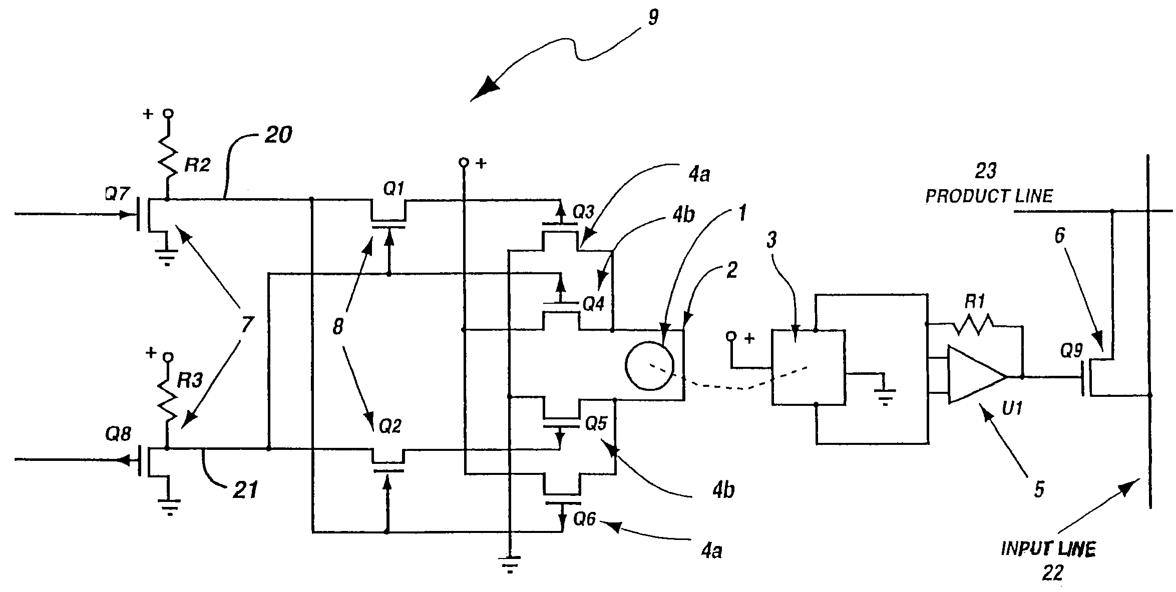
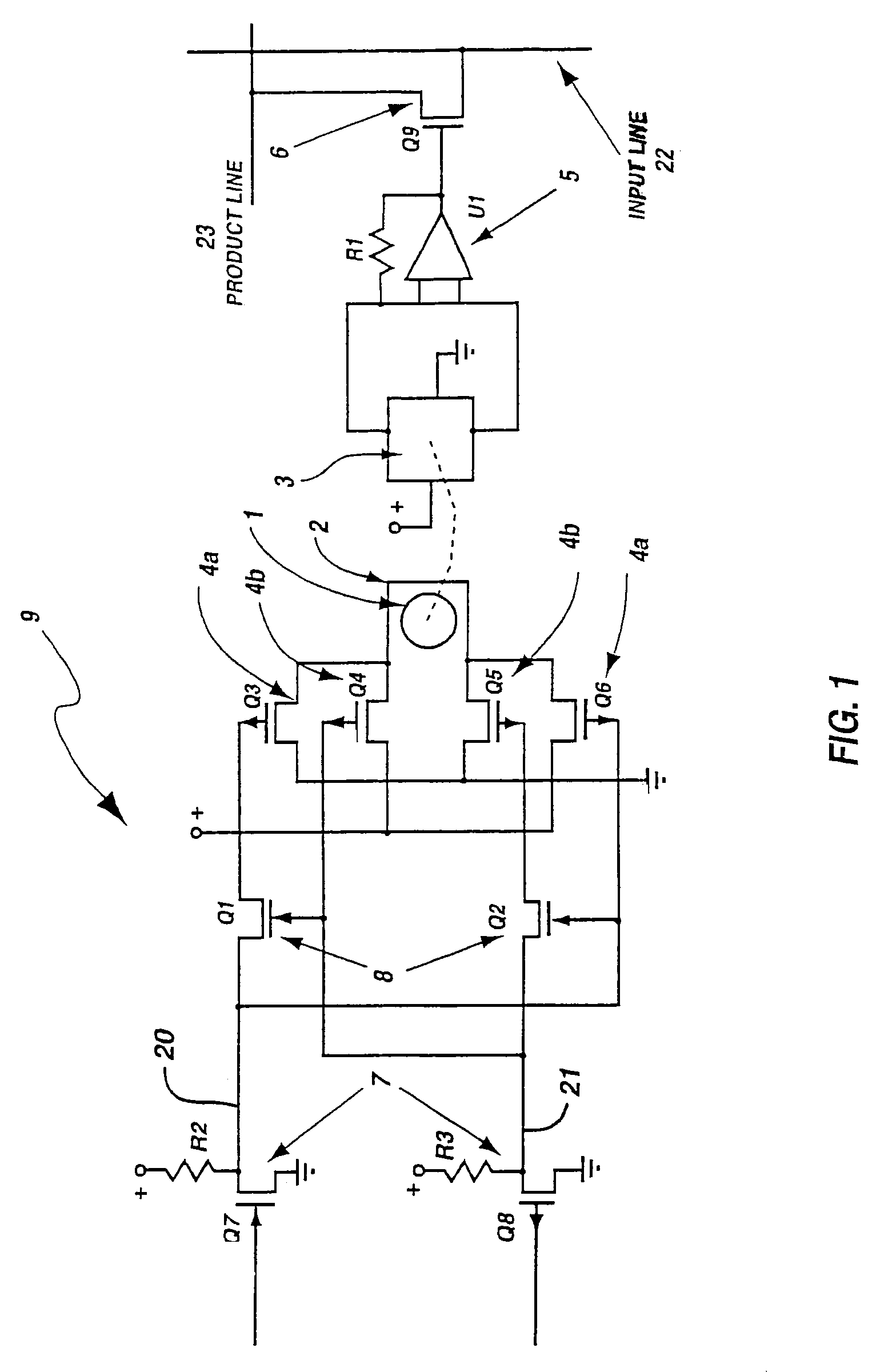
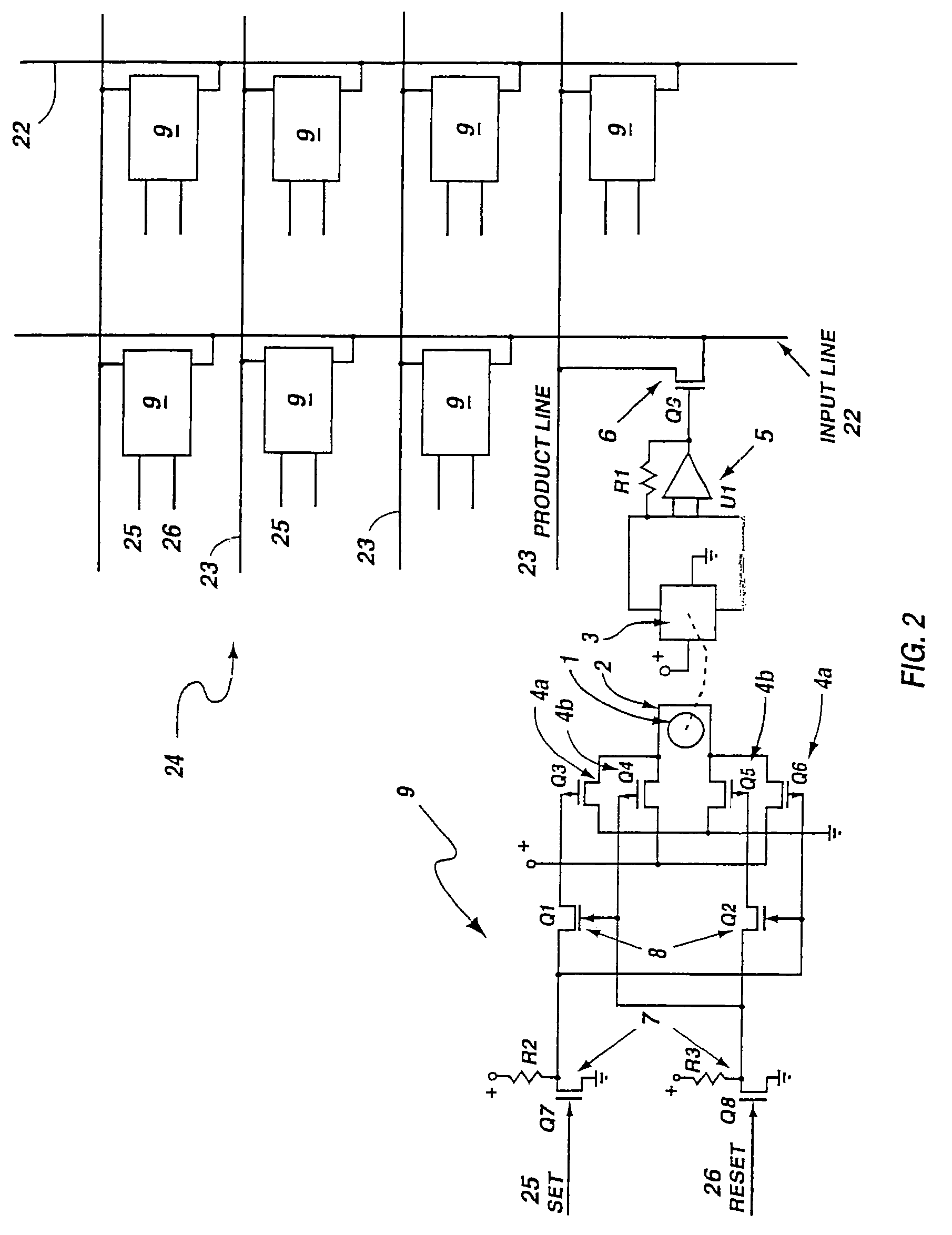
[0017]For the purposes of promoting an understanding of the principles of the invention, reference will now be made to the exemplary embodiments illustrated in the drawings, and specific language will be used to describe the same. It will nevertheless be understood that no limitation of the scope of the invention is thereby intended. Any alterations and further modifications of the inventive features illustrated herein, and any additional applications of the principles of the invention as illustrated herein, which would occur to one skilled in the relevant art and having possession of this disclosure, are to be considered within the scope of the invention.

[0018]For the purpose of providing background material which may in some respects illustrate the state of the art, the following books are herein incorporated by reference for non-essential material: “Programmable Logic Handbook,” fourth edition, by Monolithic Memories Inc., 2175 Mission College Blvd., Santa Clara, Calif.; and “Pra...


PUM


Abstract

A programmable array logic circuit whose temporary memory circuitry employs single bit non-volatile ferromagnetic memory cells. The ferromagnetic memory cells or bits store data even when there is no power provided to the circuitry, thus saving power during operation of the programmable logic circuitry, and ensuring that there is no loss of the data should there be a temporary power shut down. Additionally, the ferromagnetic cells provide for indefinite number of switching actions on the data without degradation to the capacity to store data therein. The invention provides an integrated circuit, comprising a programmable logic circuit array having product lines and input lines therein, and a storage register circuit. The storage register circuit has a ferromagnetic bit and sensor coupled to store a remnant control signal and an output transistor, coupled to be responsive to the remnant control signal on its gate, and coupled between an input and product line. Additionally, the integrated circuit may further include a logical AND array and a logical OR array.

Description

[0001]This application is a division of U.S. application Ser. No. 10 / 239,133, filed Sep. 19, 2002, now U.S. Pat. No. 6,864,711, which is incorporated herein by reference in its entirety.BACKGROUND OF THE INVENTION[0002]1. The Field of the Invention[0003]The present invention relates generally to a programmable array logic circuit employing non-volatile ferromagnetic memory cells. More particularly, the present invention uses a non-volatile ferromagnetic memory cell to temporarily store binary data.[0004]2. The Background Art[0005]Programmable logic devices have any number product sets, usually in groups of four (4), eight (8), sixteen (16) or more bits, although often in groups of ten (10). The arrays are programmed for application-specific tasks to be performed within digital electronic circuits. The fusible link types cannot be re-programmed, but those employing EEPROM and Flash can. For those PALs which use fusible links, the data in the “D” registers is lost at power off. For th...

Claims


Application Information

Patent Timeline
Patent Type & Authority Patents(United States)
IPC IPC(8): H03K19/177G11C7/22G11C11/15H03K17/687
CPCG11C7/22G11C11/15G11C11/18H03K17/6871H03K19/177H03K19/17736H03K19/1776H03K19/17772H03K19/1778H03K19/17784G11C2207/2227
Inventor LIENAU, RICHARD M.
Owner LIENAU RICHARD M
Why Eureka
Try Eureka