Microplasma emission spectrometer

a technology of emission spectrometer and microplasma, which is applied in the direction of spectrometry/spectrophotometry/monochromator, optical radiation measurement, instruments, etc., can solve the problem of limiting the application of laboratory installations

Active Publication Date: 2006-10-17
INFICON INC
View PDF21 Cites 36 Cited by
  • Summary
  • Abstract
  • Description
  • Claims
  • Application Information

AI Technical Summary

Problems solved by technology

Such systems are relatively large having a footprint on the order of sever

Method used


Image

  • Microplasma emission spectrometer
  • Microplasma emission spectrometer
  • Microplasma emission spectrometer

Examples


Embodiment Construction

[0010]Most known systems for performing chemical analysis have plasma sources that have relatively large dimensions, which typically are on order of 5–10 cm. The input power necessary to generate a plasma density in the W / cm3 range for such a plasma source may be as high as several kilowatts. These known systems have several disadvantages. One disadvantage is that these systems are not suitable for portable operation with a battery powered power supply. Another disadvantage is that the power supplies in these systems are relatively large, complex and expensive.

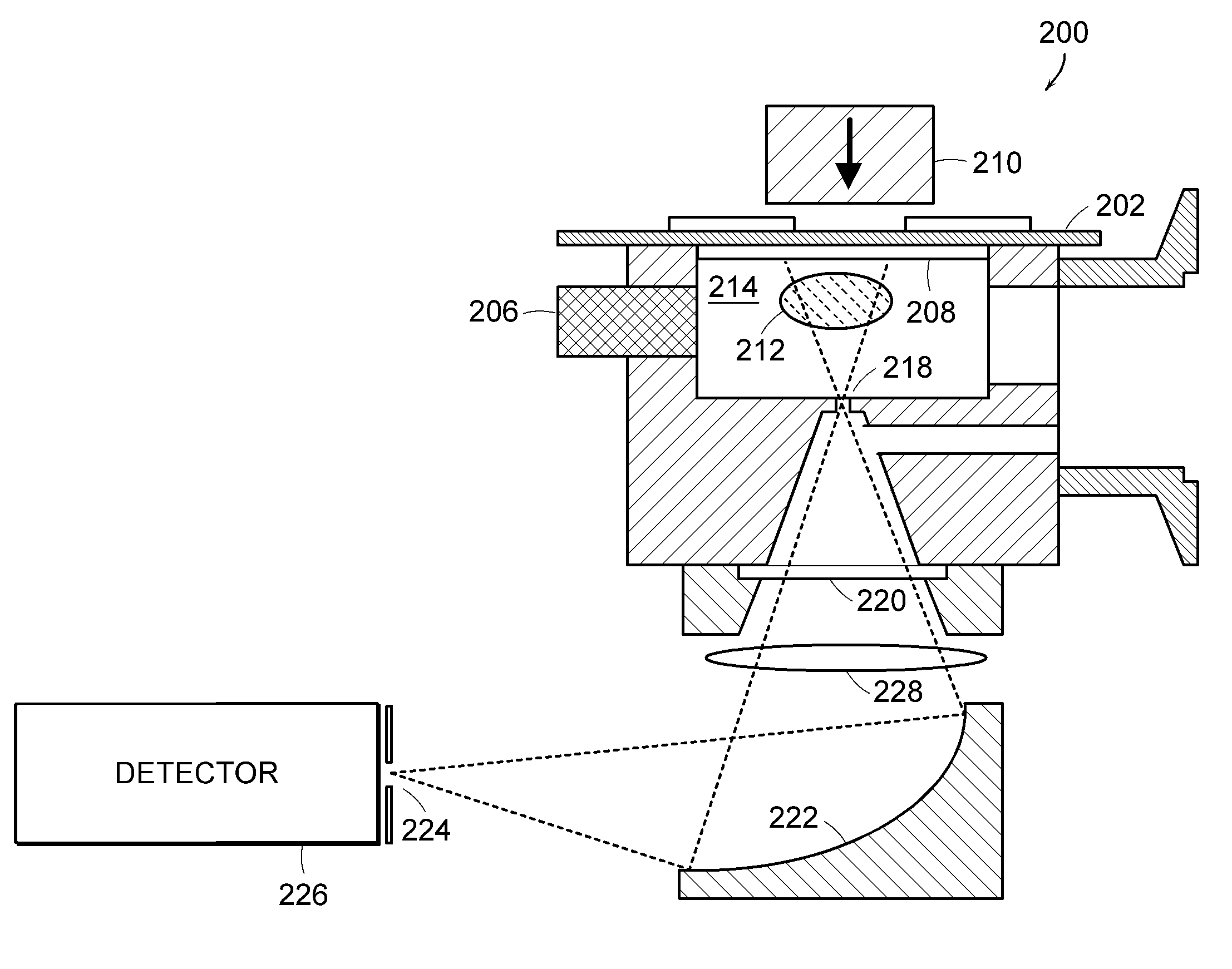
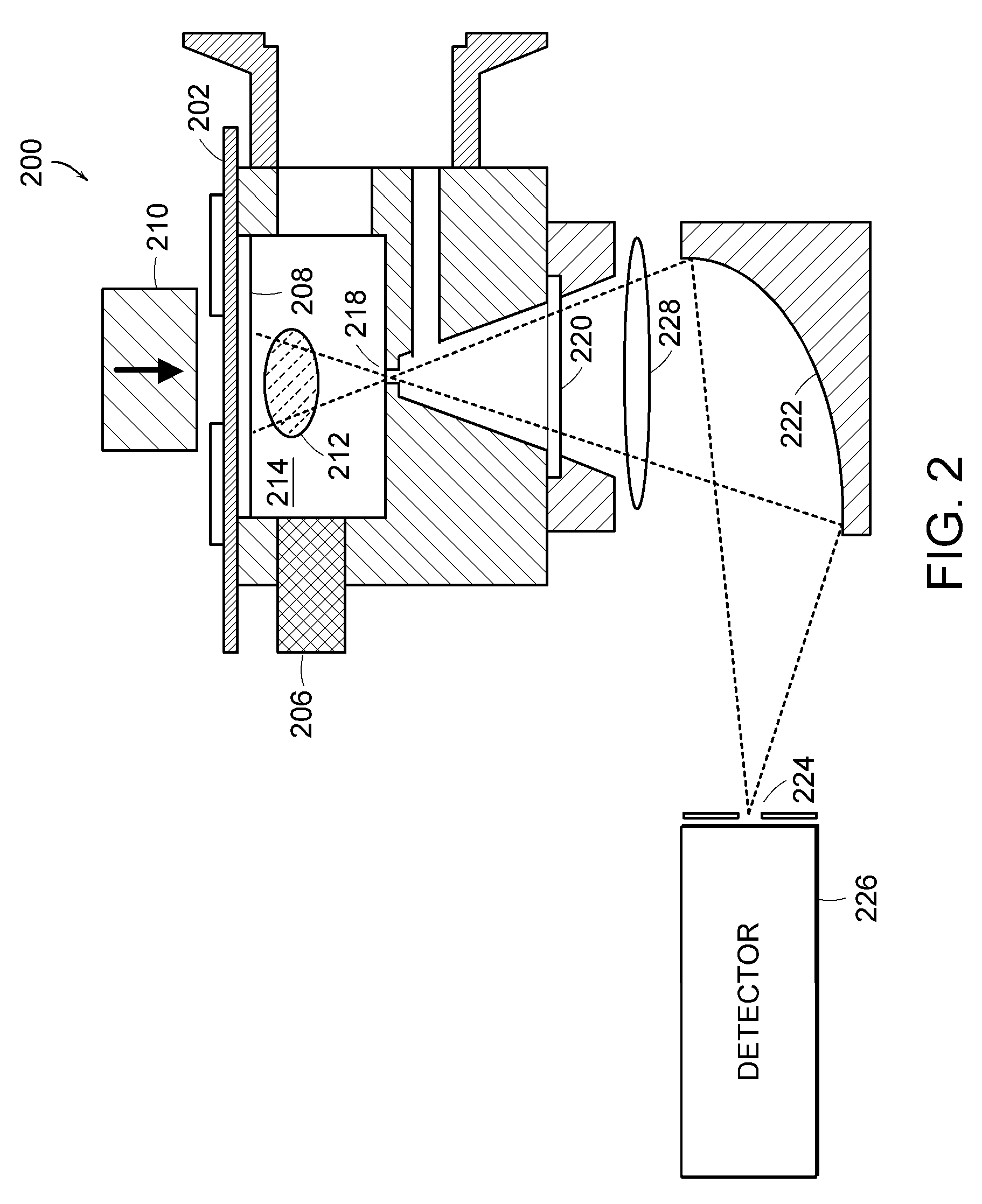
[0011]In addition, these known systems for performing chemical analysis are relatively inefficient because the fraction of the optical emission generated that is actually coupled to the optical detector is typically very small due to the low numerical aperture of the optical collection systems. Thus, only a very small region, which is typically millimeter sized, is effectively imaged onto the spectrometer entrance slit and the...


PUM


Abstract

A microplasma emission spectrometer is described that includes a chamber for confining a sample volume of gas. A microplasma source that includes a resonant antenna structure generates a microplasma in the chamber from the sample volume of gas. A RF power supply provides power to the resonant antenna structure that generates the microplasma from the sample volume of gas. A spectrally sensitive detector is optically coupled to the microplasma. The entrance of the spectrally sensitive detector has dimensions and is positioned so that emissions from at least one-tenth of a total volume of the microplasma are transmitted through the entrance of the spectrally sensitive detector.

Description

CROSS REFERENCE TO RELATED APPLICATIONS[0001]This application claims priority to provisional patent application Ser. No. 60 / 452,235, filed on Mar. 5, 2003, the entire disclosure of which is incorporated herein by reference.BACKGROUND OF INVENTION[0002]Many industrial and scientific applications require chemical analysis of gas and liquid phase materials to obtain data for these applications. Also, many environmental applications require chemical analysis of gas and liquid phase materials to obtain data useful for health and safety analysis.[0003]Numerous techniques and apparatus have been developed to perform chemical analysis of gas and liquid phase materials. One common analytical technique used for gas phase analysis is plasma emission spectrometry. Plasma emission spectrometry is performed by electrically exciting gas to form a plasma where one or more species undergo excitation and decay via emission at UV, visible, or infrared wavelengths. Detailed spectral analysis of these e...

Claims


Application Information

Patent Timeline
IPC IPC(8): G01J3/30
CPCG01J3/02G01J3/027G01J3/443G01N21/68H05H1/30
Inventor DOUGHTY, FRANK C.
Owner INFICON INC
Why Eureka
Try Eureka