High-speed parallel cross bar switch

a cross bar switch, high-speed technology, applied in the direction of data switching networks, digital transmission, electrical equipment, etc., can solve the problems of increasing complexity and high cost of data switches from which the networks are assembled

Inactive Publication Date: 2006-10-17
TELLABS OPERATIONS
View PDF9 Cites 8 Cited by
  • Summary
  • Abstract
  • Description
  • Claims
  • Application Information

AI Technical Summary

Problems solved by technology

As a result, the data switches from which the networks are

Method used


Image

  • High-speed parallel cross bar switch
  • High-speed parallel cross bar switch
  • High-speed parallel cross bar switch

Examples


Embodiment Construction

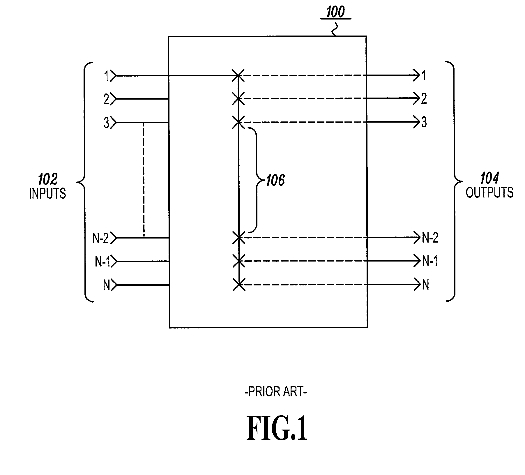
[0012]FIG. 1 shows a simplified schematic diagram of a prior art cross bar switch 100. The cross bar switch receives data (not shown) from a data source (not shown) at one or more input terminals 102. Data at an input 102, such as input 102-1, can be routed to any one of the outputs 104 by way of relays or relay equivalents (typically comprised of switching logic devices) 106 by which data is synchronously clocked from an input 102 to an output 104. By controlling the appropriate relay or relay equivalent, data from a source can be re-directed to a destination coupled to one or more of the output ports 104.

[0013]Those skilled in the art understand the operation of a cross bar switch, a detailed understanding of which is not required for purposes of this disclosure. Cross bar switches are readily available from manufacturers such as Lucent Technologies, Inc., Nortel Networks, Inc., PMC Sierra Inc., and Advanced Micro Circuits Inc.(AMCC) as those skilled in the art will recognize.

[001...


PUM


Abstract

Low speed switches operated under the common control of a global scheduler can be used to switch high speed data while preserving packet ordering if the incoming packets are queued in a temporal order. By operating several low speed switches in parallel, a high-speed switching capacity can be realized.

Description

RELATED APPLICATION[0001]This application claims the benefit of U.S. Provisional Application No. 60 / 250,298 filed Nov. 29, 2000.FIELD OF THE INVENTION[0002]This invention relates to data switching systems. In particular, this invention relates to a method and apparatus for providing a relatively high-speed switching capability using several relatively low speed switching systems operated in parallel.BACKGROUND OF THE INVENTION[0003]The Internet and its ever-increasing use, by a rapidly growing number of users continues to test the limits of switching equipment. Data networks that comprise the Internet are required to carry greater amounts of data, faster and faster. As a result, the data switches from which the networks are assembled are becoming increasingly complex and expensive.[0004]Internet protocol (IP) data networks now routinely carry data at rates that are well over 1 gigabit per second. Switching equipment that is fast enough to handle such data rates, needs to be able to ...

Claims


Application Information

Patent Timeline
IPC IPC(8): H04L12/56
CPCH04L12/5601H04L49/106H04L49/1576H04L49/255H04L2012/565H04L2012/5681
Inventor SHARMA, VISHALMNEIMNEH, SAADEDDINE
Owner TELLABS OPERATIONS
Why Eureka
Try Eureka