Rod member receiving apparatus

a technology of receiving apparatus and rod member, which is applied in the direction of mechanical conveyors, instruments, computing, etc., can solve the problems of cigarette rods not being able to be carried along the conveying path, cigarette rods cannot be transferred from the catcher drum to the transfer drum, and wrinkles easily formed on the wrapping paper of the cigarette rod, etc., to achieve the effect of stabilizing the forward movemen

Inactive Publication Date: 2006-10-17
JAPAN TOBACCO INC
View PDF7 Cites 4 Cited by
  • Summary
  • Abstract
  • Description
  • Claims
  • Application Information

AI Technical Summary

Benefits of technology

[0028]The catcher drum can further comprise assist means for assisting the rod member to move forward in each of the receiving grooves. This assist means generates a flow of air flowing in the direction of the forward movement of the rod member, in each of the receiving grooves. This assist means stabilizes the forward movement of rod members, so that the rod members are prevented from becoming jammed in the receiving grooves.

Problems solved by technology

In this situation, the cigarette rod rubs against the inner surface of the receiving groove, and wrinkles are easily formed on the wrapping paper of the cigarette rod.
As a result, the cigarette rod cannot be transferred from the catcher drum to the transfer drum, hence cannot be carried along the conveying path.

Method used


Image

  • Rod member receiving apparatus
  • Rod member receiving apparatus
  • Rod member receiving apparatus

Examples


Embodiment Construction

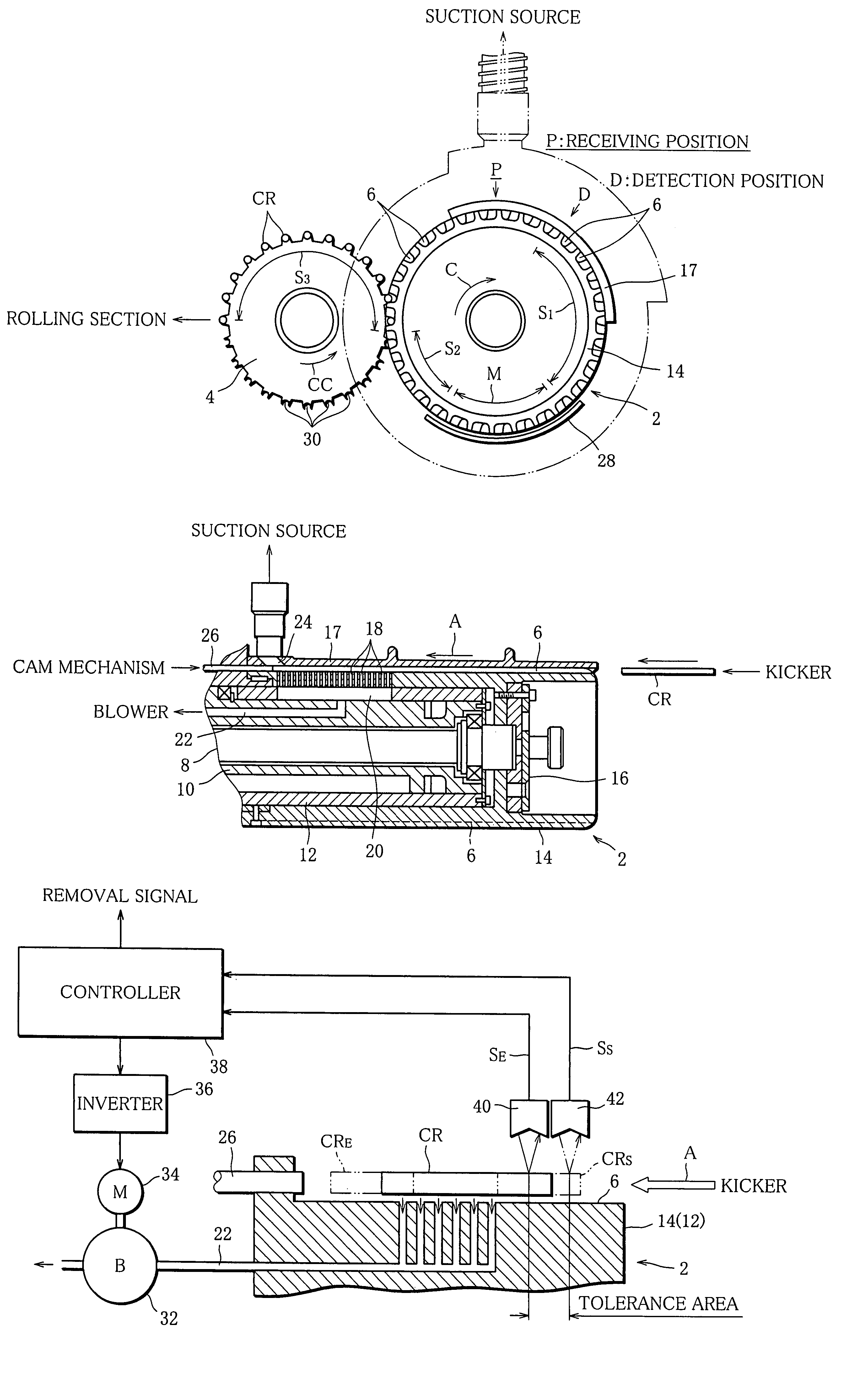
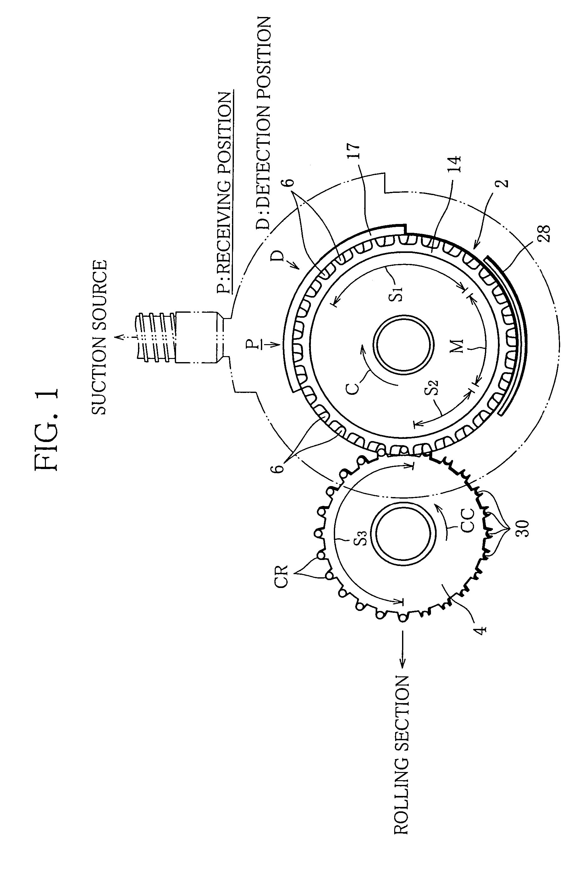
[0040]FIG. 1 shows a beginning part of a drum train of a filter cigarette making machine. The drum train comprises a plurality of grooved drums. The grooved drums are arranged in line, adjacent to each other. Any of the grooved drums rotates in a direction opposite to the direction in which a grooved drum adjacent thereto rotates. The drum train thus forms a conveying path along which cigarette rods are carried.

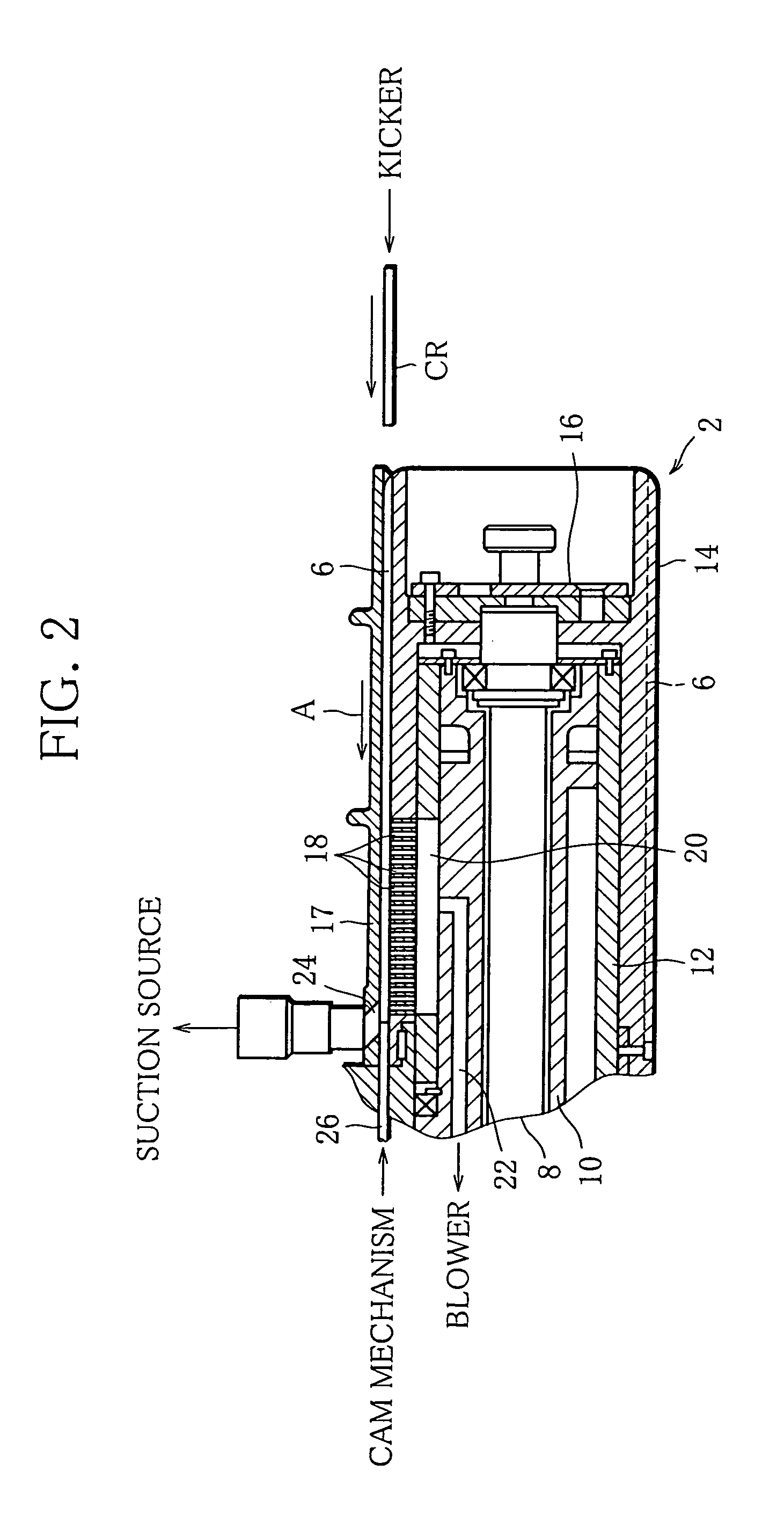
[0041]The beginning part of the drum train includes two grooved drums, namely a catcher drum 2 and a transfer drum 4. The catcher drum 2 has a plurality of receiving grooves 6 in an outer circumferential surface thereof. The receiving grooves 6 are arranged at regular intervals in the circumferential direction of the catcher drum 2. Each of the receiving grooves 6 extends in the axial direction of the catcher drum 2, and has an inlet that is open at an end face of the catcher drum 2 and a closed end.

[0042]As the catcher drum 2 rotates, the receiving grooves 6 pass a receiving...


PUM


Abstract

A receiving apparatus for a filter cigarette making machine comprises a rotatable catcher drum (2). The drum (2) has receiving grooves (6) in its outer circumferential surface, for each receiving a cigarette rod (CR). A rod (CR) received in the groove (6) moves forward into a braking area therein. In the braking area, the rod (CR) receives braking force due to suction and is stopped. A pair of limit sensors (40, 42) are arranged outside the drum (2). The sensors (40,42) optically detect a rear end of the rod (CR), and on the basis of the result of this detection, whether a stop position at which the rod is stopped is within a tolerance area or not is determined. On the basis of the result of this determination, a controller (38) regulates the braking force exerted on rods (CR) to thereby control the stop position of the rods (CR). Then, a pusher (26) pushes the rod (CR) from its stop position back to a normal position, in each of the grooves (6).

Description

[0001]This application is a Continuation of copending PCT International Application No. PCT / JP03 / 01335 filed on Feb. 7, 2003, which designated the United States, and on which priority is claimed under 35 U.S.C. § 120. This application also claims priority under 35 U.S.C. § 119(a) on Patent Application No(s). 2002-051663 filed in Japan on Feb. 27, 2002. The entire contents of each of the above documents are hereby incorporated by reference.TECHNICAL FIELD[0002]The present invention relates to a rod member receiving apparatus, particularly a receiving apparatus suitable as a cigarette rod receiving apparatus in a filter cigarette making machine.BACKGROUND ART[0003]A filter cigarette making machine has a predetermined conveying path, and cigarette rods are supplied to the conveying path and carried along the carrying path. While carried along the conveying path, each cigarette rod is cut into two equal parts to form two cigarettes.[0004]Then, on the conveying path, a cigarette / plug ass...

Claims


Application Information

Patent Timeline
Patent Type & Authority Patents(United States)
IPC IPC(8): G06F7/00A24C5/32A24C5/47
CPCA24C5/327A24C5/478
Inventor OKAMOTO, HIROSHIHORIKAWA, SYOZO
Owner JAPAN TOBACCO INC
Why Eureka
Try Eureka