
Continuous type motorcycle hub heat treatment furnace

A technology for heat treatment furnaces and motorcycles, applied in heat treatment furnaces, heat treatment equipment, heat treatment process control, etc., can solve the problems of hub heating, low space and temperature utilization, and affect processing, so as to achieve uniform heating, improve space utilization, non-deformable effect

Inactive Publication Date: 2018-04-06
CHONGQING QINGYI MOLD MFG
View PDF0 Cites 0 Cited by
  • Summary
  • Abstract
  • Description
  • Claims
  • Application Information

AI Technical Summary

Problems solved by technology

This kind of processing mode has low processing efficiency, limited processing capacity, low utilization rate of space and temperature in the furnace, high operating intensity, and is not suitable for large-scale continuous production.
Continuous processing, the main way of conveying in the furnace is the furnace roller type, the furnace roller is placed at the bottom of the furnace, the heated hub is placed on the furnace roller, and the furnace roller rotates slowly to push the hub forward. Usually, the hub is stacked in a material frame For heat treatment, due to the high stacking density of the hubs in the stacking method, the hubs are stacked on each other, and the hubs cannot be heated well, resulting in uneven heating of the hubs and affecting the heat treatment effect
In addition, the way of stacking may cause deformation of the hub under stress, which will affect subsequent processing

Method used


Image

  • Continuous type motorcycle hub heat treatment furnace
  • Continuous type motorcycle hub heat treatment furnace
  • Continuous type motorcycle hub heat treatment furnace

Examples


Embodiment 1

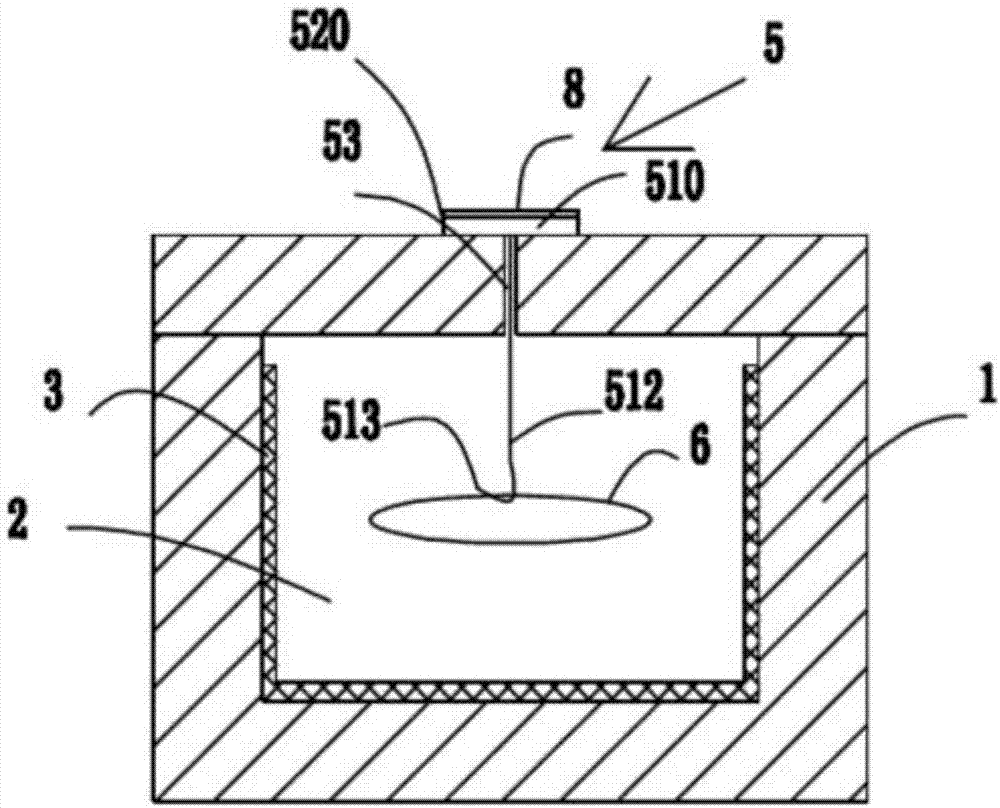
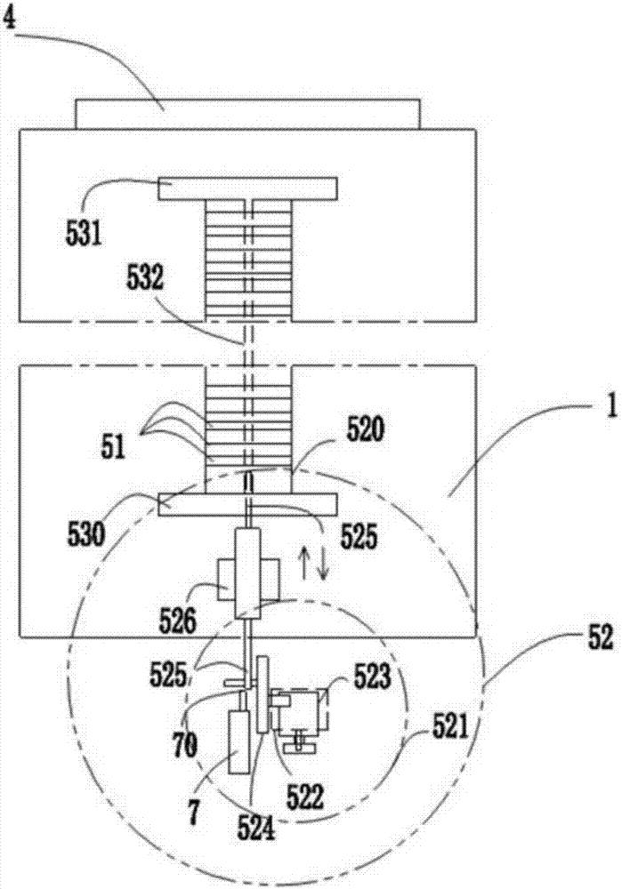
[0025] figure 2 It is a schematic sectional view of Embodiment 1 of the continuous motorcycle hub heat treatment furnace; image 3 It is a schematic top view of Embodiment 1; Figure 4 Schematic diagram of the structure of the hanger device. Such as figure 2 and image 3 As shown, the present invention provides a continuous heat treatment furnace for motorcycle wheels, a continuous heat treatment furnace for motorcycle wheels, which includes a furnace body 1, a heat treatment chamber 2, a heating body 3, and a furnace door 4, and the heating body 3 is located in the heat treatment chamber. It is heated in the chamber 2, and the furnace door 4 is arranged at one end of the furnace body 1, which can be opened or closed, and also includes a hanger moving system 5, which includes a plurality of hanger devices 51, The pushing mechanism 52 and the "I"-shaped opening 53 provided above the furnace body 1;

[0026] The hanger device 51, the hanger device 51 is in the shape of a ...

Embodiment 2

[0035] in, Figure 5 It is a schematic sectional view of embodiment two of the continuous motorcycle hub heat treatment furnace, as Figure 5 As shown, the heat treatment furnace of this embodiment includes two sets of hanger moving systems 5, and the systems are arranged side by side. This way can improve the space utilization rate in the furnace, so that the efficiency of heat treatment is higher.


PUM


Abstract

The invention relates to a continuous heat treatment furnace for motorcycle wheel hubs, comprising a furnace body (1), a heat treatment chamber (2), a heating body (3), and a furnace door (4), wherein the heating body (3) is located in the heat treatment chamber (2). ), and also includes a pylon moving system (5), the pylon moving system (5) comprising a plurality of pylon devices (51), a pushing mechanism (52) and a The opening (53); the hanger device (51) hangs the motorcycle wheel hub (6) and enters through the first transverse opening (530) of the furnace body (1); the hanger device (51) is driven along the longitudinal direction by the driving device The opening (532) moves forward, and the end of the heat treatment is successively raised from the second transverse opening (531). During the treatment process, the motorcycle wheel hubs (6) are arranged side by side, which overcomes the stacking method, the wheel hub is not easily deformed by force, and at the same time, the heating is more uniform, and the space utilization rate in the furnace is improved.

Description

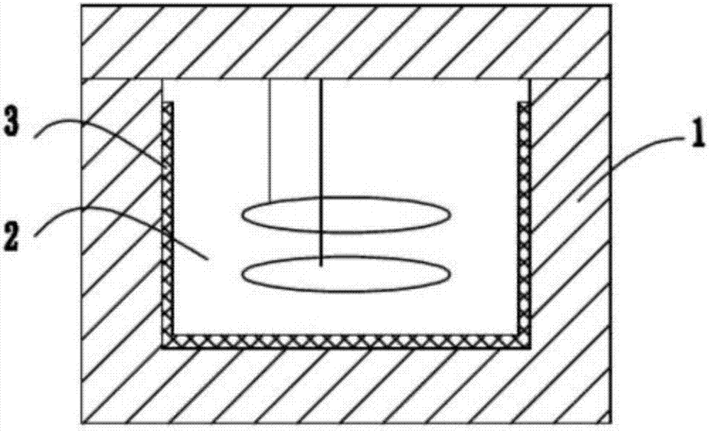
technical field [0001] The invention relates to the field of electric furnaces, in particular to a continuous heat treatment furnace for motorcycle hubs. Background technique [0002] At present, the special heat treatment furnaces for motorcycle hubs are generally split-type treatment and continuous treatment. Such as figure 1 As shown, the split-back treatment is to put the hubs into the furnace in batches, heat treatment for a period of time until the treatment is completed, and then take out the hubs for a new round of heat treatment. This kind of processing mode has low processing efficiency, limited processing capacity, low utilization rate of space and temperature in the furnace, high work operation intensity, and is not suitable for large-scale continuous production. Continuous processing, the main way of conveying in the furnace is the furnace roller type, the furnace roller is placed at the bottom of the furnace, the heated hub is placed on the furnace roller, an...

Claims


Application Information

Patent Timeline
IPC IPC(8): C21D9/34C21D11/00
CPCC21D9/34C21D9/0018C21D11/00
Inventor 秦锋
Owner CHONGQING QINGYI MOLD MFG
Learn More