Driving assist system for vehicle

a technology for driving assistance and vehicles, applied in the direction of machinery control, process and machine control, instruments, etc., can solve the problems of not enabling the operator to verify whether, and it is difficult for the operator to quickly determine which of the two vehicles

Inactive Publication Date: 2006-10-17
NISSAN MOTOR CO LTD
View PDF60 Cites 16 Cited by
  • Summary
  • Abstract
  • Description
  • Claims
  • Application Information

AI Technical Summary

Benefits of technology

[0005]However, the system described above does not enable the operator to verify whether or not any preceding vehicle has been detected without checking the monitor display or the like. In particular, if another vehicle cuts in between the subject vehicle and the preceding vehicle and thus the condition surrounding the subject vehicle changes in a discontinuous manner while the automatic cruise control is engaged, it is difficult for the operator to promptly determine which of the two vehicles, i.e., the cut-in vehicle (the vehicle that has just cut in front of the subject vehicle) or the initial preceding vehicle, is currently being detected by the automatic cruise control system and which vehicle is being targeted by the system.

Problems solved by technology

However, the system described above does not enable the operator to verify whether or not any preceding vehicle has been detected without checking the monitor display or the like.
In particular, if another vehicle cuts in between the subject vehicle and the preceding vehicle and thus the condition surrounding the subject vehicle changes in a discontinuous manner while the automatic cruise control is engaged, it is difficult for the operator to promptly determine which of the two vehicles, i.e., the cut-in vehicle (the vehicle that has just cut in front of the subject vehicle) or the initial preceding vehicle, is currently being detected by the automatic cruise control system and which vehicle is being targeted by the system.

Method used


Image

  • Driving assist system for vehicle
  • Driving assist system for vehicle
  • Driving assist system for vehicle

Examples


first embodiment

[0031

[0032]The following is an explanation of the first embodiment of the vehicle driving assist system according to the present invention, given in reference to the drawings.

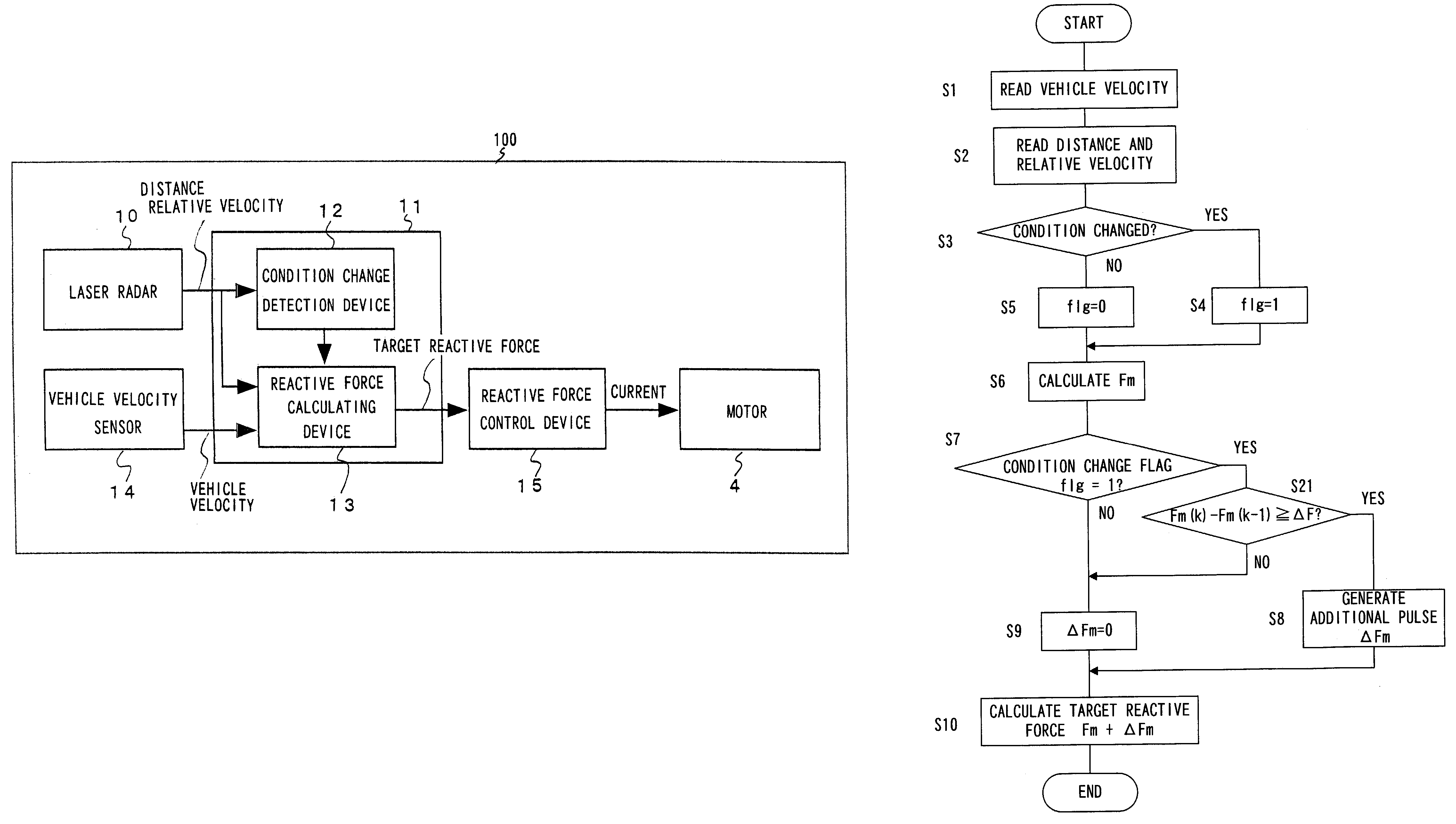
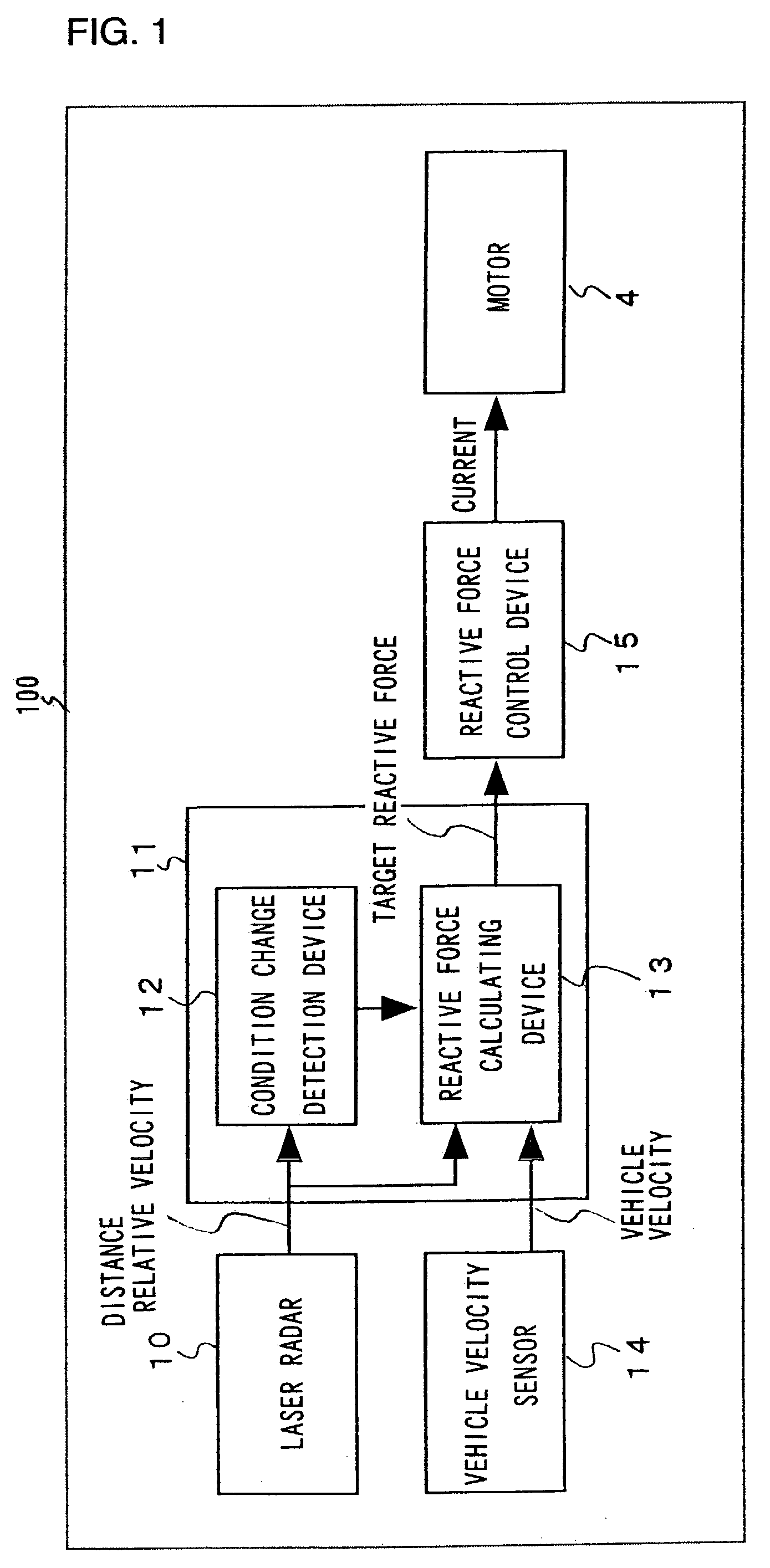
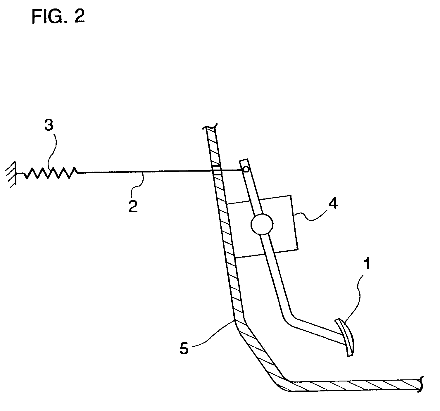
[0033]FIG. 1 is a system diagram of the structure adopted in a vehicle driving assist system 100 achieved in the embodiment and FIG. 2 shows the structure of the essential portion of an accelerator pedal 1 employed in the driving assist system 100. FIG. 9 shows how the vehicle driving assist system 100 is installed in a vehicle. It is to be noted that the following explanation focuses on an example in which the vehicle driving assist system 100 is adopted in a so-called automatic vehicle tracking system in which the distance between vehicles is automatically controlled in conformance to the extent to which the accelerator pedal 1 is operated.

[0034]As shown in FIG. 2, the accelerator pedal 1 is supported by a spring 3 via a wire 2 and a servomotor 4 that is linked to the rotating shaft of the accelerator pedal 1...

second embodiment

[0061

[0062]Now, in reference to FIG. 6, the second embodiment of the present invention is explained.

[0063]The contents of the processing executed by the controller 11 in the second embodiment is differentiated from the first embodiment. FIG. 6 presents a flowchart of an example of the processing procedure of the program executed by the controller 11 in the second embodiment. It is to be noted that in FIG. 6 the same step numbers are assigned to steps in which processing similar to that in FIG. 3 is executed and that the following explanation focuses on the difference from the processing shown in FIG. 3.

[0064]As shown in FIG. 6, after making a decision in step S7 that the condition change flag “flg=1”, i.e., that a condition change has occurred, the operation proceeds to step S21. In step S21, the target reactive force Fm (k−1) previously calculated through an arithmetic operation immediately before the occurrence of the condition change is subtracted from the target reactive force F...

third embodiment

[0067

[0068]The third embodiment of the present invention is explained in reference to FIGS. 7 and 8.

[0069]The specific contents of the processing executed by the controller 11 differentiate the third embodiment from the first embodiment. FIG. 7 presents a flowchart of an example of the processing executed by the controller 11 in the third embodiment. It is to be noted that in FIG. 7 the same step numbers are assigned to steps in which processing identical to that in FIG. 3 is executed and that the following explanation focuses on the difference from the processing shown in FIG. 3.

[0070]As shown in FIG. 7, after making a decision in step S7 that the condition change flag “flg=1”, i.e., that a condition change has occurred, the operation proceeds to step S31. In step S31, the target reactive force Fm(k−1) previously calculated through an arithmetic operation immediately before the occurrence of the condition change is subtracted from the target reactive force Fm(k) calculated through ...


PUM


Abstract

A vehicle driving assist system comprises a condition recognition device that detects a vehicle condition and a traveling environment around a subject vehicle; a reactive force application device that applies a reactive force, in conformance to the vehicle condition and the travelling environment around the subject vehicle, to an operation device; a condition change detection device that detects a condition change occurring around the subject vehicle; and a reactive force variation device that adjusts the reactive force applied by the reactive force application device in a period of time, when the condition change detection device detects that a condition around the subject vehicle has changed discontinuously.

Description

BACKGROUND OF THE INVENTION[0001]1. Field of the Invention[0002]The present invention relates to a vehicle driving assist system that assists an operator to operate a vehicle, a method adopted in the vehicle driving assist system and a vehicle equipped with the system.[0003]2. Description of the Related Art[0004]Systems employed to assist an operator to operate a vehicle include that disclosed in Japanese Laid Open Patent Publication No. 2000-54860. This system adjusts the reactive force against an accelerator pedal operation based upon the distance between a preceding vehicle and the subject vehicle detected with a laser radar or the like while automatic cruise control is implemented in the subject vehicle. For instance, the accelerator pedal reactive force is set to heavy as a warning to the operator if the detected distance between the vehicles becomes smaller than a predetermined value, and the accelerator pedal reactive force is also set to a greater value during the automatic ...

Claims


Application Information

Patent Timeline
Patent Type & Authority Patents(United States)
IPC IPC(8): G06F17/00B60K28/02B60K26/02B60K26/04B60K28/10B60K31/00B60K31/18
CPCB60K26/021B60K31/0008B60W30/16B60W2050/143
Inventor EGAMI, MASAHIRO
Owner NISSAN MOTOR CO LTD
Why Eureka
Try Eureka