Method and system for extinguishing a fire

a fire and extinguishing technology, applied in fire rescue, medical science, dental surgery, etc., can solve the problem of insignificant water produced by fires, and achieve the effects of accurate design, limited propagation of hot gases, and efficient cooling

Inactive Publication Date: 2006-10-24
MARIOFF CORP OY
View PDF13 Cites 23 Cited by
  • Summary
  • Abstract
  • Description
  • Claims
  • Application Information

AI Technical Summary

Benefits of technology

[0005]The object of the present invention is to achieve a completely new type of solution that makes it possible to focus the extinguishing power of a fire extinguishing system to the actual fire area, either completely without a separate detection system or by using a less sensitive and therefore cheaper detection system. Such a fire extinguishing system can be so dimensioned that it will be feasible in practice. Another object of the invention is to achieve an efficient fire extinguishing system designed to be applied for extinguishing fires occurring in tunnels.
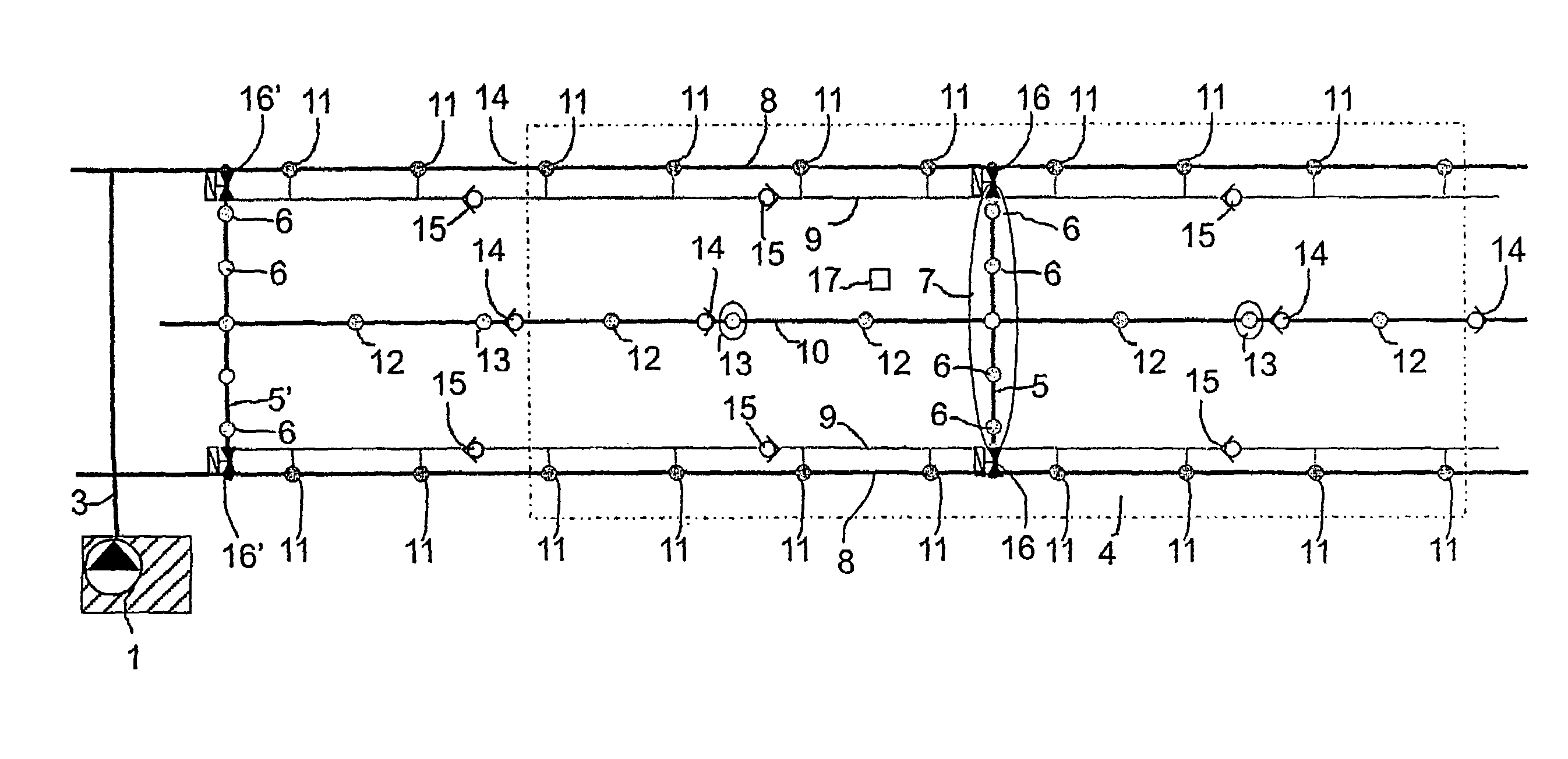
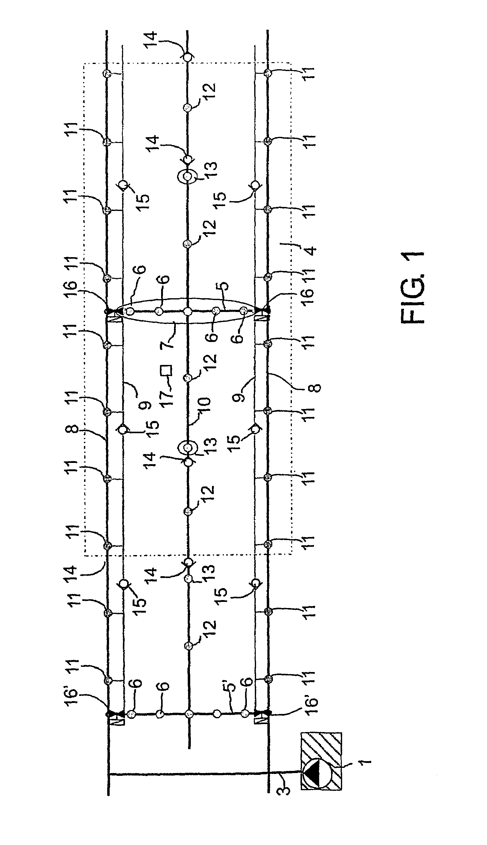
[0011]The solution of the invention has numerous significant advantages. By using the solution of the Invention, an extinguishing system can be more accurately designed because the occurrences of spraying heads being triggered in a wrong zone are either completely prevented or at least minimized. By creating a curtain of extinguishing medium, efficient cooling is produced in the space and the propagation of hot gases is limited. In addition, when the spraying heads are pre-activated and the protecting means covering the heat-activated triggering means of the second spraying heads are removed, the possibility of spurious triggering is minimized. The curtain of extinguishing medium further reduces the possibility of spurious triggering of the next curtains and the associated zones. By using heat-activated triggering means in the second spraying heads, the extinguishing effect of the extinguishing system of the invention can be applied to the area on fire.

Problems solved by technology

At first, one or more curtains of extinguishing medium in a wrong zone may be triggered, but the amount of water produced by them is insignificant as compared with the amount of water in a complete zone.

Method used


Image

  • Method and system for extinguishing a fire
  • Method and system for extinguishing a fire
  • Method and system for extinguishing a fire

Examples


Embodiment Construction

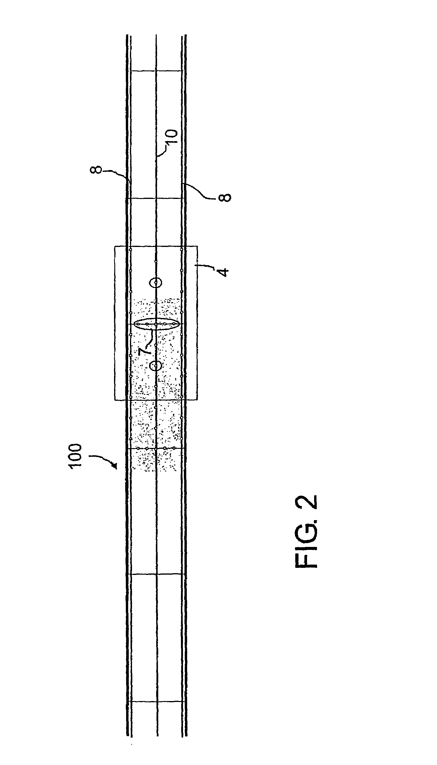
[0016]FIGS. 1 and 2 present a solution according to the invention especially in conjunction with a tunnel. 100. The figures show a part of a fire extinguishing system in the tunnel in simplified and diagrammatic form. The system typically comprises a pump unit 1 and a pipeline 3, through which an extinguishing medium, pumped by the pump, is supplied into the piping network of the tunnel when the system is active. In the figure, the piping network comprises two main pipelines 8 and between these a central main pipeline 10. The figure presents the system in a diagrammatic top view. Between the main pipelines 8 there is formed at least one transverse pipe 5, which preferably connects the main pipelines as well as the optional central main pipeline 10 to each other. The transverse pipe 5 is provided with first spraying heads 6, which in an activated state are mainly intended to produce a curtain 7 of extinguishing medium, typically a curtain of aqueous extinguishing medium, in a transve...


PUM


Abstract

Method for extinguishing a fire in a space, especially in a tunnel or equivalent, in which method an extinguishing medium is sprayed in the space by means of spraying heads. In a first stage of the method, the flow and temperature of the hot gases produced by the fire are influenced by spraying an extinguishing medium into the space, especially by creating in the space at least one curtain (7) of extinguishing medium, and at least some spraying heads (11, 12) in the space are pre-activated into a state of readiness, and in a second stage at least one spraying head is activated to produce a spray of extinguishing medium. The invention also concerns an apparatus.

Description

BACKGROUND OF THE INVENTION[0001]The present invention relates to a method as defined in the preamble of claim 1 for extinguishing a fire in a space, especially in a tunnel or equivalent, in which method an extinguishing medium is sprayed in the space by means of spraying heads.[0002]The invention also relates to a fire extinguishing apparatus as defined in the preamble of claim 11.[0003]In recent times, the question of firefighting in tunnels, such as road and railway tunnels and equivalent, has emerged. Several destructive fires have occurred in tunnels because they generally have no permanent fire extinguishing systems. The traditionally imaginable fire extinguishing systems are either sprinkler systems or zonewise triggered spraying systems. In sprinkler systems, the sprinklers are triggered individually by the action of heat. In a tunnel application, they involve the problem that, as a consequence of the fast propagation of hot gases, a very large number of them are triggered e...

Claims


Application Information

Patent Timeline
Patent Type & Authority Patents(United States)
IPC IPC(8): A62C2/00A62C2/08A62C3/00A62C35/00A62C37/00A62C37/10A62C3/02A62C35/58A62C35/68A62C37/11
CPCA62C2/08A62C3/00A62C3/0221A62C37/11A62C3/0292A62C35/58A62C3/0264A62C31/02A62C35/00
Inventor SUNDHOLM, GORANTUOMISAARI, MAARIT
Owner MARIOFF CORP OY
Why Eureka
Try Eureka