Electromagnetically actuated gas valve

a gas valve and electric motor technology, applied in the direction of valve details, valve arrangement, valve operating means/release devices, etc., can solve the problems of high magnetic force only, needle valves, and require a minimum amount of greasing for wear-and-tear-free operation, etc., to achieve the effect of improving sealing

Active Publication Date: 2006-10-24
HOERBIGER KOMPRESSORTECHNIK HLDG GMBH
View PDF12 Cites 22 Cited by
  • Summary
  • Abstract
  • Description
  • Claims
  • Application Information

AI Technical Summary

Benefits of technology

[0010]This object is solved according to the present invention with a gas valve of the kind referred to above in that the sealing plate is arranged on the discharge side of the valve seat in a manner that is known in the art and connected to a stamp that is guided in a longitudinal direction extending through the valve seat and the solenoid, with the solenoid being arranged on the incoming flow side before the valve seat; and the stamp carries an anchor plate acting in conjunction with the solenoid on its end that is directed away from the sealing plate; and a Venturi tube meter is arranged after the sealing plate on the discharge side featuring a cross-section which is smaller than the sum of the effective flow-through cross-sections between valve seat and opened sealing plate. The movable sealing plate is thus arranged on the side of the valve seat that is directed toward the combustion chamber, pulled and closed against the seat by the return spring counteracting the pressure of the supplied fuel gas. The direction of action of the solenoid, that controllably opens the valve, is reversed relative to the mentioned known embodied examples, whereby the combustion pressure acting from the combustion chamber is absorbed by the sealing plate and transferred by the sealing plate to the valve seat. This way, the combustion pressure is utilized in order to improve the sealing between combustion chamber and fuel gas supply.
[0011]The closing force of the return spring can be easily and advantageously adjusted to the fuel gas pressure in this context so that the solenoid only has to overcome small resulting forces for opening. The preferably used pot magnet supplies very high forces in the pulled-in position, i.e., with a minimal residual air gap, thereby allowing the counter-pressure on the side of the combustion chamber indeed to rise while the valve is opened without the valve closing prematurely or inadvertently. Consequently, thanks to the large cross-sections that can be controlled in the manner described, a very compact construction type with small required magnetic forces results which makes it possible to use the gas valve according to the invention also in relatively small gas engines ranging all the way to passenger car driving engines.
[0013]Even though the gas valve according to the invention can also in principle be configured with flow-through openings of the valve seat featuring meandering-shaped nesting or of a grate or spiral type, for construction-specific reasons a preferred embodied example provides a valve seat with at least two concentrically arranged, essentially ring-shaped flow-through openings that can be closed off by the corresponding barrier surfaces of the sealing plate and that allow in the open state of the gas valve for a discharge across essentially ring-shaped, concentrically arranged discharge openings of the sealing plate. Therefore, with regard to the realization of the flow-through openings and the corresponding barrier surfaces and discharge openings, there results a similar realization as in U.S. Pat. No. 6,182,943 that was referred to previously, allowing for the simple and robust design of the barrier elements acting in conjunction.
[0014]It is possible to envision only a centrally arranged stamp that is axially guided in sliding bearings for the transfer of the switching movement of the anchor plate acting in conjunction with the solenoid, thereby allowing for simple and precise guiding and valve actuation. The return spring can be configured, for example, as a spiral-shaped compression spring arranged concentrically relative to the stamp in a central recess of the solenoid or magnet carrier and supported on the one side inside this recess while supported on the other side on the anchoring plate, resulting overall in a simple and symmetrical valve design.
[0015]On the discharge side, after the Venturi tube meter, it is possible, in a further embodied example, to arrange a Laval nozzle in series that extends to the opening, in particular, in an effort to improve the utilization of the internal energy of the supplied fuel gas and to achieve a stream impulse that is as large as possible for the better homogenization of the combustible mixture.
[0016]A further embodied example of the invention provides for integrating a springy stop into the solenoid or magnet carrier in order to effect a stroke limit of the sealing plate; it is preferably worked together with the end surfaces of the magnet legs allowing for the possibility of minimizing the tolerance errors that are responsible for the residual air gap of the solenoid.

Problems solved by technology

Moreover, needle valves have the disadvantage that they require a minimum amount of greasing for wear-and-tear-free operation, which does not take place during operation with gases, transported or stored in liquid form in the vehicle, due to the extremely low dew point.
But the high magnetic forces can only be realized at very small distances or air gaps, which means that the stroke available for switching the magnet is also very minimal.
A special difficulty of the combustion process involving direct fuel allocation into the combustion chamber results from the circumstance that the injectors are exposed to the combustion pressure and the high combustion temperatures.
With lower fuel pressures, this task is difficult to achieve because the magnets that have the sufficient strength both with regard to construction volume as well as dynamic reaction behavior are not suitable.
But this embodiment has several disadvantages: the forces that are introduced from the pressure-compensating piston to the valve plate have the ability to effect an undesired deformation of the valve plate resulting in the partial opening of the valve translating into impermissible leakage.
Moreover, the problem emerges that combustion exhaust may penetrate into the pressure equalization system contaminating or clogging it.
Consequently, it is no longer possible to ensure the proper functioning of the apparatus.

Method used


Image

  • Electromagnetically actuated gas valve
  • Electromagnetically actuated gas valve
  • Electromagnetically actuated gas valve

Examples


Embodiment Construction

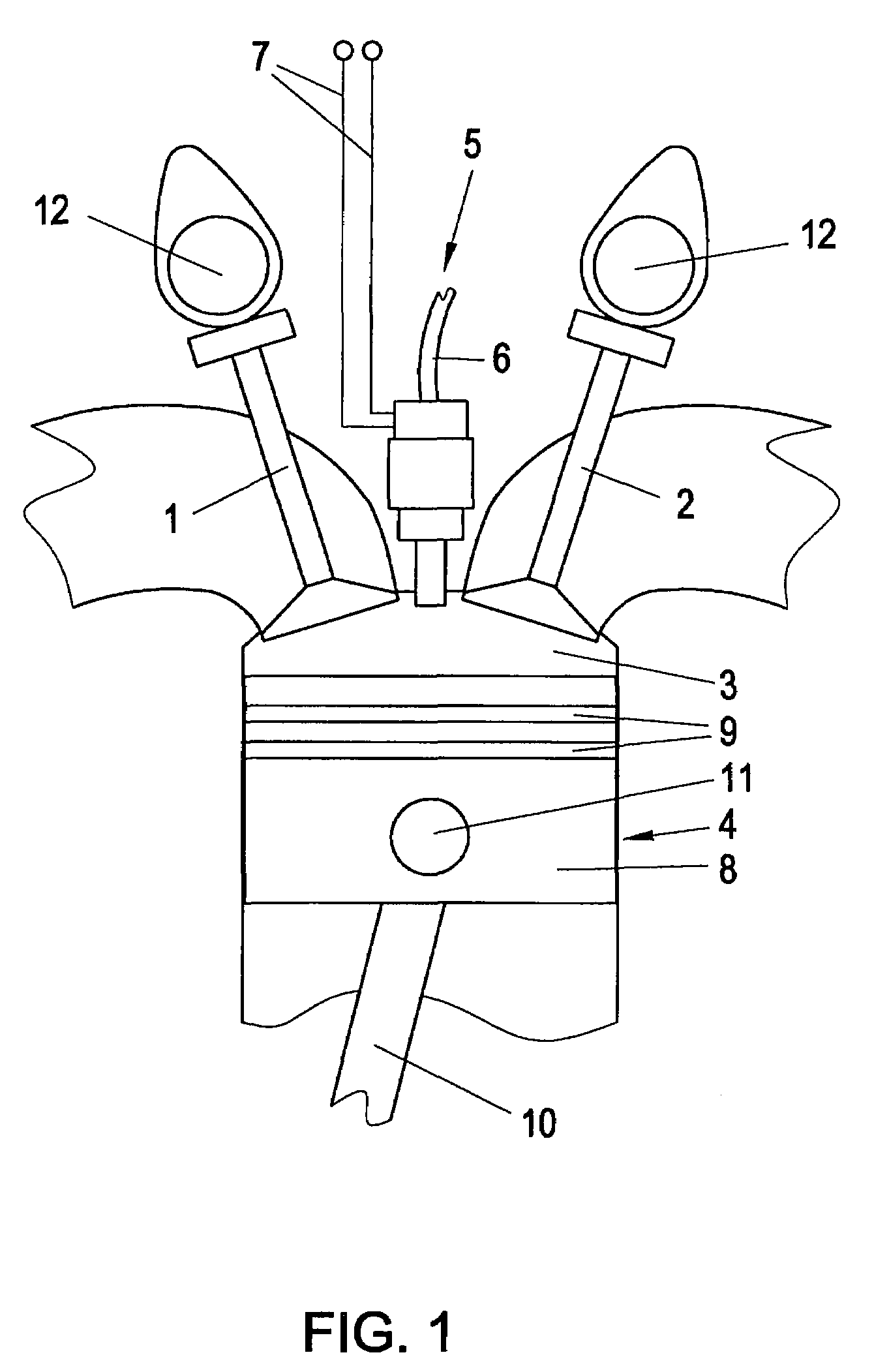
[0021]In accordance with FIG. 1, a gas valve 5 is used between intake valve and exhaust valve 1,2 on the upper limit of the combustion chamber 3 of a gas engine 4, that is only schematically hinted at, for the purpose of the clocked import of fuel gas that is supplied via the line 6. The electrical connection lines 7 are used, if necessary, for activating the electromagnetic actuation of the gas valve 5 whereupon the valve is opened against the force of a return spring—for details, refer to FIG. 2 of the following description.

[0022]Only for reasons of completeness of FIG. 1, reference is being made also to the reciprocating piston 8 including piston ring 9, connecting rod 10, and piston pin 11 as well as the camshafts 12 that are provided at the top for the actuation of the valves 1,2.

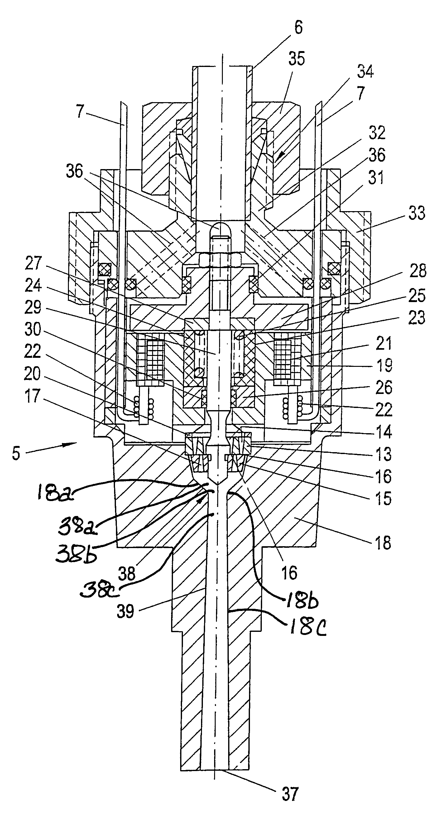
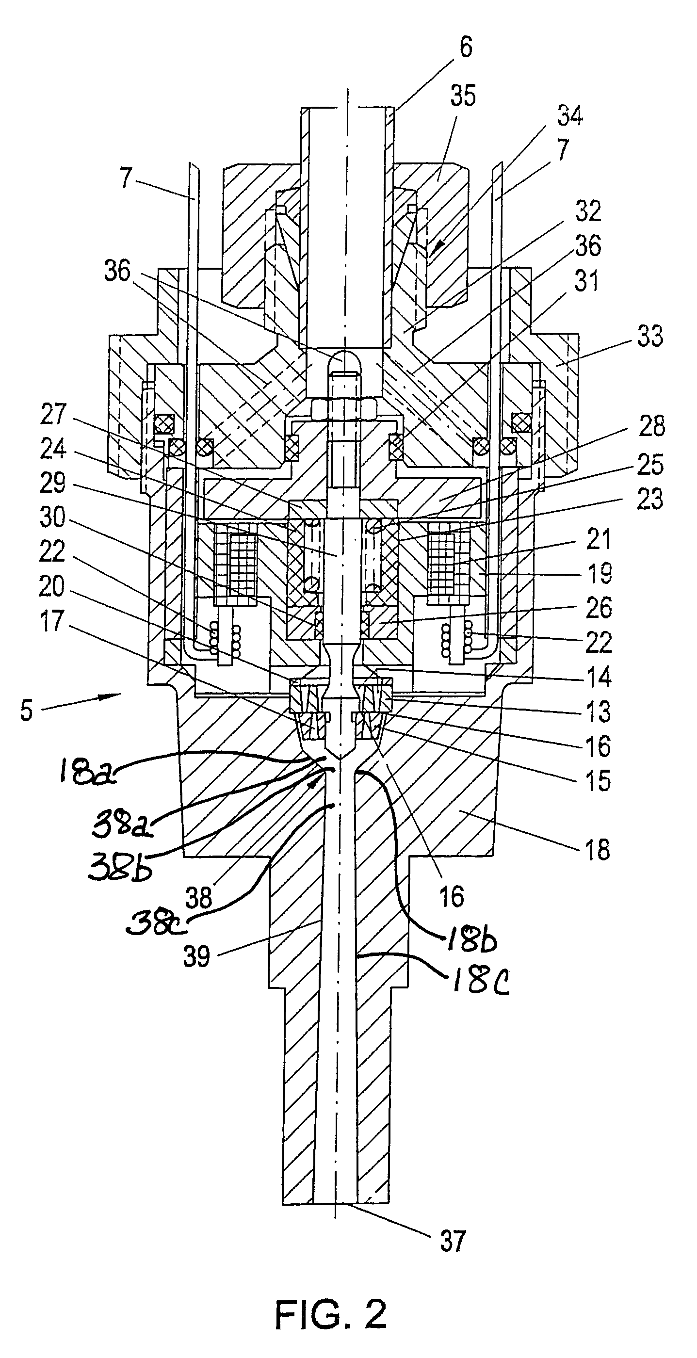
[0023]The gas valve 5 has, in accordance with FIG. 2, a valve seat 13 with two concentrically arranged, essentially ring-shaped flow-through openings 14 and a movable sealing plate 15 that is guided pe...


PUM


Abstract

An electromagnetically actuated gas valve (5) for gas engines (4) includes a valve seat (13) that has at least one flow-through opening (14) and a corresponding sealing plate (15), with the sealing plate being movably arranged and guided essentially perpendicularly relative to the valve seat (13), with barrier surfaces (16) and discharge openings (17). The sealing plate (15) is loaded against the valve seat (13) by means of a return spring (25) and can be lifted for the purpose of opening it via a solenoid (21). In order to allow for the secure sealing and easy switchability even in the presence of the effect of the combustion chamber pressure, the sealing plate (15) is arranged on the discharge side of the valve seat (13) and connected by means of a stamp (29), which extends through the valve seat (13), with the anchor plate (28) of the solenoid (21). A Venturi tube meter (38) is arranged on the discharge side after the sealing plate (15) for the purpose of calibrating the flow-through correction value and for suppressing any dispersions due to manufacturing variations with regard to the effective flow cross-section, and the cross-section of the Venturi tube meter (38) is smaller than the sum of the effective flow-through cross-sections between valve seat (13) and opened sealing plate (15).

Description

BACKGROUND OF THE INVENTION[0001]1. Field of the Invention[0002]The invention relates to an electromagnetically actuated gas valve, in particular for the fuel gas supply in gas engines including a valve seat that has at least one flow-through opening and a sealing plate, movably arranged and guided essentially perpendicularly relative to the valve seat, which has at least one discharge opening, arranged adjacent to a barrier surface that corresponds to the flow-through opening of the valve seat, in order to allow for the overall essentially linear flow-through of the fuel gas through the gas valve; the sealing plate is loaded against the valve seat by means of a return spring and can be lifted relative to the opening via a solenoid; and the flow-through opening of the valve seat has, in comparison with a circular surface of the same cross-section, a large sealing edge length; and the opening stroke of the sealing plate is small.[0003]2. The Prior Art[0004]Magnetically actuated injec...

Claims


Application Information

Patent Timeline
Patent Type & Authority Patents(United States)
IPC IPC(8): F16K31/02F16K1/42F16K31/06
CPCF16K1/42F16K31/0655
Inventor STEINRUCK, PETERSPIEGL, BERNHARDREIN, KARLRANEGGER, GERHARD
Owner HOERBIGER KOMPRESSORTECHNIK HLDG GMBH
Why Eureka
Try Eureka