Methods and apparatus for mixing fluids

a technology of fluid mixing and apparatus, applied in the direction of machine/engine, combustion air/fuel air treatment, separation process, etc., can solve the problem of just as detrimental liquid depth, and achieve the effect of reducing the hydrophilicity of liquid crossflow and high skirt heigh

Inactive Publication Date: 2006-10-24
FLUOR TECH CORP
View PDF14 Cites 4 Cited by
  • Summary
  • Abstract
  • Description
  • Claims
  • Application Information

AI Technical Summary

Benefits of technology

[0013]By increasing skirt height, the hydraulic resistance to liquid crossflow is reduced. The preferred skirt height for a specific application is dependent upon, among other things, the liquid volumetric rate passing through the tray. For low liquid rates, bubble caps having a skirt height of no less than 1.5 inches is preferred. At higher liquid rates, bubble caps having a skirt height of at least 2.0 inches is more preferred, and at still higher liquid rates, bubble caps having a skirt height of at least 2.5 inches is more preferred. At very high liquid rates, as may be encountered in very large reactors, bubble caps having a skirt height of 3 inches or higher are contemplated. The unusually high skirt heights are preferably achieved by using an especially long riser rather than using an especially short cap.

Problems solved by technology

These variations in the liquid depth are just as detrimental to the uniformity of liquid distribution as physical variations from levelness of the tray deck itself.

Method used


Image

  • Methods and apparatus for mixing fluids
  • Methods and apparatus for mixing fluids
  • Methods and apparatus for mixing fluids

Examples


Embodiment Construction

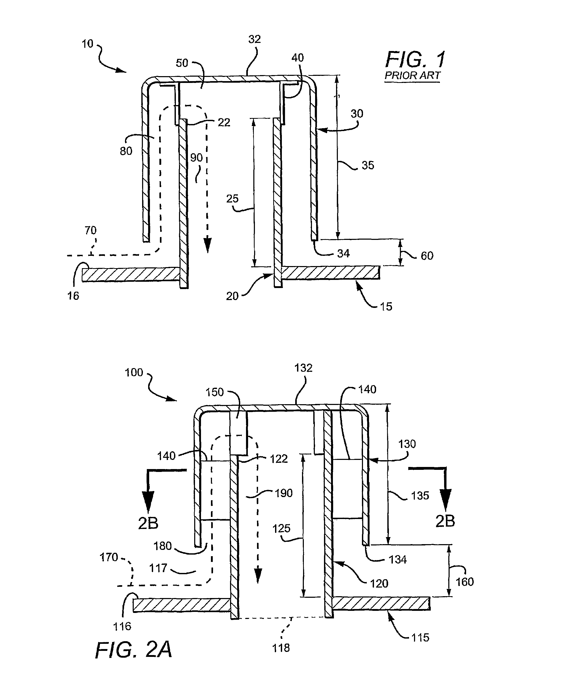
[0028]In FIG. 1, a prior art bubble cap 10 generally comprises a riser 20 and a cap 30 separated by a spacer 40. The bubble cap 10 is attached to a distribution plate 15. The spacer 40 is very small with respect to the lengths of both riser 20 and cap 30, and the skirt height 60 is less than 1.5 inches. The fluid flow path 70 through the bubble cap is generally in the shape of an inverted “U”.

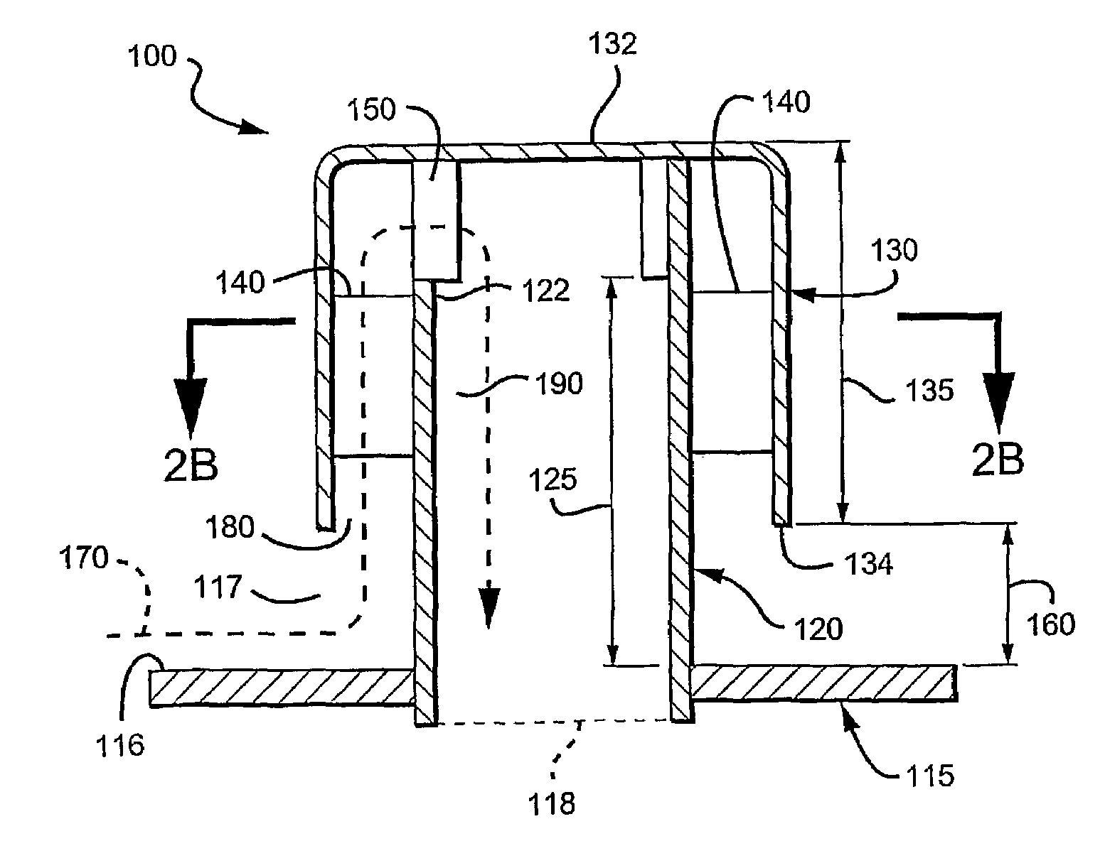
[0029]In FIGS. 2A and 2B, a bubble cap 100 generally comprises a riser 120 and a cap 130 separated by a plurality of dividers 140. The bubble cap cooperates with a distribution plate 115 to locally mix the fluids. (As used herein, the term “fluid” means anything that flows, including especially a vapor phase or a liquid phase, or a mixture comprising at least two phases. The term also includes any fluid that is mixed and distributed in a commercial process.)

[0030]The riser 120 has a top 122 and a riser height 125 defined by a distance between the top 122 of the riser 120 and the top 116 of the ...


PUM


Abstract

A bubble cap (100) has a riser (120) and a cap (130), separated by a divider (140) that extends to a length at least 50% of a distance measured between the top of the riser (122) and the bottom of the cap (134). In another aspect, the riser (120) and cap (130) cooperate to provide a skirt height (160) of no less than 1.5″. More preferred bubble caps (400) have a relatively high skirt height (460) or long slit length (497), or both. In yet another aspect, flow-redirecting vanes (610) and plates (630) cooperate to provide a rough distribution of fluids to subsequent distribution tray (650).

Description

[0001]This application is a national phase application of International patent application with the serial number PCT / US01 / 13436, which was filed Apr. 24, 2001, and which claims priority to provisional U.S. application with the Ser. No. 60 / 257,414, filed Dec. 21, 2000, and incorporated by reference herein.FIELD OF THE INVENTION[0002]The field of the invention relates to fluid mixing and distribution.BACKGROUND OF THE INVENTION[0003]Many commercial processes involve mixing of fluids, including especially catalytic reactors and large fractionation columns. Such mixing is not always a simple matter, especially where the fluid has multiple phases (such as liquids and gases / vapors), and where large volumes are being rapidly mixed. Numerous mixing apparatus are known, and some of these are described in U.S. Pat. No. 6,098,965 to Jacobs et al. (August 2000), which is incorporated herein by reference in its entirety. Jacobs et al. teach several improvements, some of which involve bubble cap...

Claims


Application Information

Patent Timeline
Patent Type & Authority Patents(United States)
IPC IPC(8): B01F3/04B01D3/20B01J8/04
CPCB01D3/205B01J8/0492Y10T137/86212Y10T137/85938
Inventor JACOBS, GARRY E.STUPIN, STEVEN W.MILLIKEN, ADAM S.
Owner FLUOR TECH CORP
Why Eureka
Try Eureka