Protection for external electrode fluorescent lamp system

a fluorescent lamp and fluorescent lamp technology, applied in the direction of electric variable regulation, process and machine control, instruments, etc., can solve the problems of reducing the life of the eefl, affecting the operation of the eefl, so as to reduce the total current

Inactive Publication Date: 2006-10-24
O2 MICRO INT LTD
View PDF6 Cites 49 Cited by
  • Summary
  • Abstract
  • Description
  • Claims
  • Application Information

AI Technical Summary

Benefits of technology

[0005]A driving circuit with protection function for driving a set of cold cathode flourescent lamps in accordance with the present invention includes: a transformer connected to the set of cold cathode flourescent lamps; a switching network connected to the transformer which delivers power to the transformer; a sensing circuit connected to the set of cold cathode flourescent lamps which detects disconnection if one cold cathode flourescent lamp is disconnected; and a controller connected to the switching network which controls the switching network to reduce the total current supplied to the cold cathode flourescent lamps which remain connected, if the sensing circuit detects that one cold cathode flourescent lamp is disconnected.

Problems solved by technology

Due to the increased panel size and number of lamps used in large LCD panel applications, the wiring becomes a complex burden both in manufacturing and cost.
One drawback occurs when one of the EEFLs 40 is not connected properly.
This will degrade the life time of the EEFL.

Method used


Image

  • Protection for external electrode fluorescent lamp system
  • Protection for external electrode fluorescent lamp system
  • Protection for external electrode fluorescent lamp system

Examples


Embodiment Construction

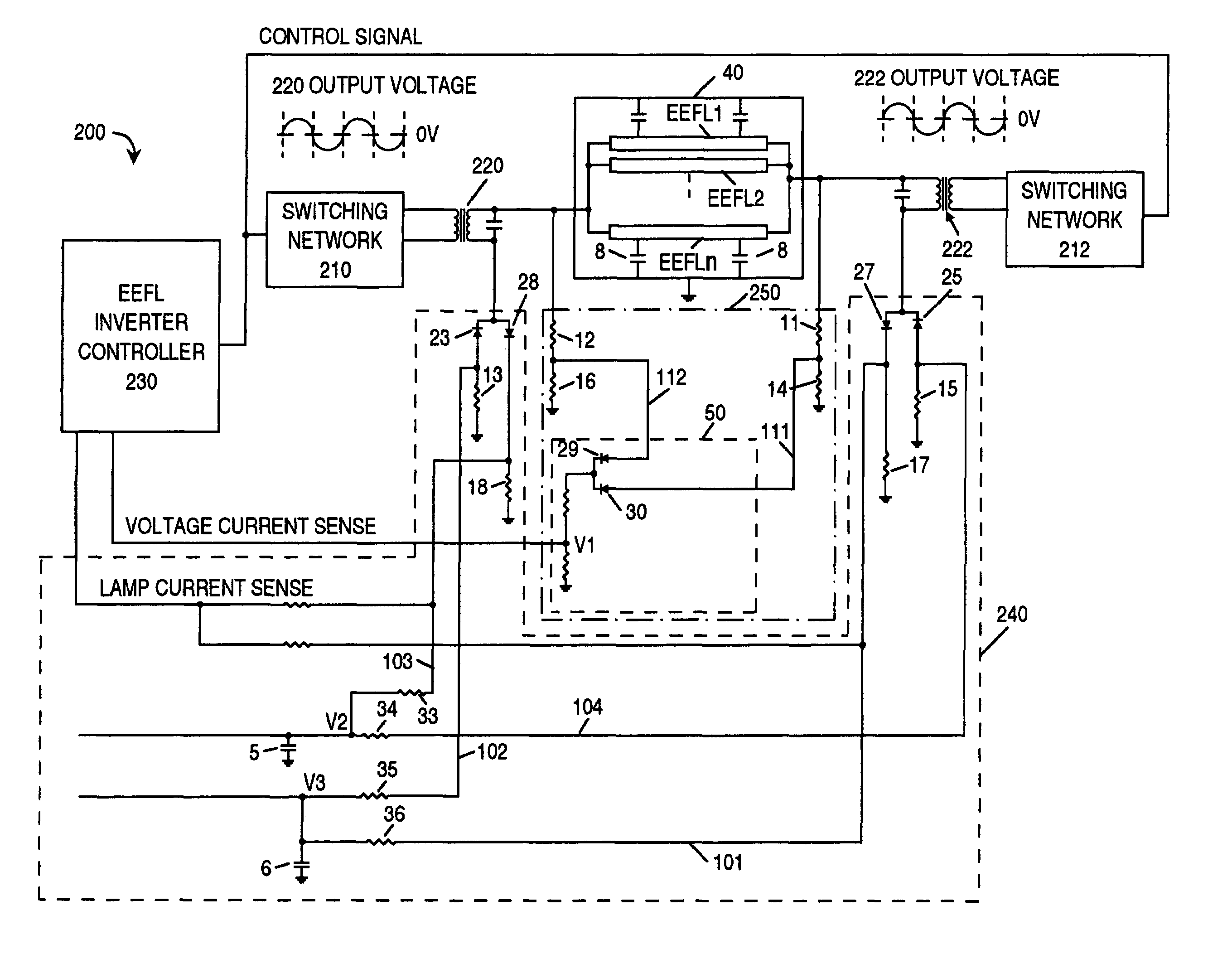
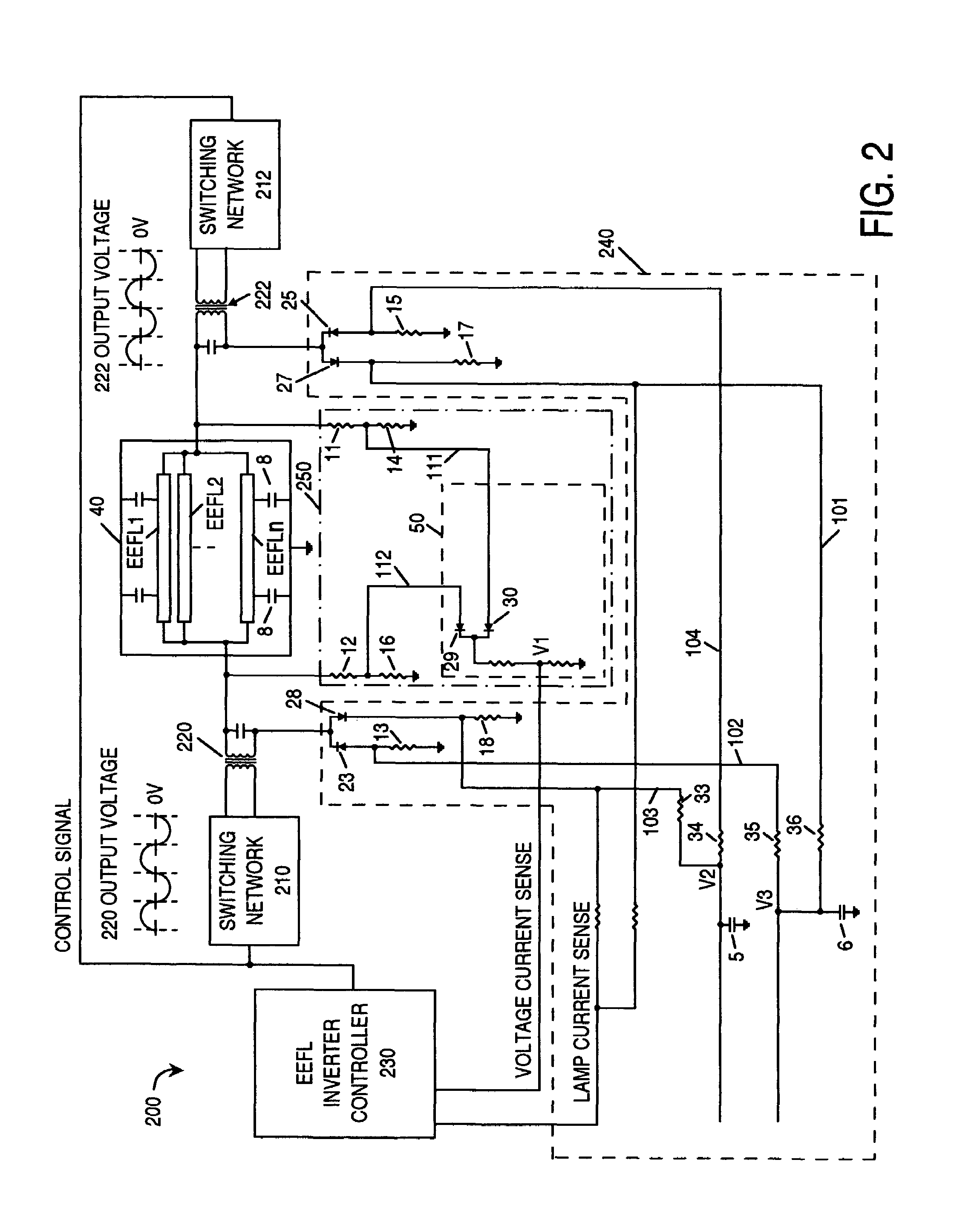
[0017]Turning to FIG. 2, a circuit diagram of a driving system 10′ with protection function in accordance with the present invention is depicted. Generally, system 10′ includes a plurality of EEFLs 40 (EEFL(1), EEFL(2) . . . , EEFL(n)); transformer 220 and 222; switching network 210 and 212; EEFL inverter controller 230; first end sensing circuit 240 and second end sensing circuit 250.

[0018]Transformer 220 and 222 which delivery power to EEFLs 40 (EEFL(1), EEFL(2) . . . , EEFL(n)) are connected to the two plates of the EEFLs 40 respectively. As shown in FIG. 2, switching network 210 is connected to transformer 220. Similarly, switching network 212 is connected to transformer 222. Switching network 210 and 212 can include a DC / AC converter, such as the push-pull, half-bridge, full-bridge type DC / AC converter. EEFL inverter controller 230 sends control signals to both switching networks 210 and 212, thus regulate the current supplied to the EEFLs. Purposely, transformer 220 and 222 ar...


PUM


Abstract

The present invention provides a driving circuit with protection function for driving a set of external electrode fluorescent lamps (EEFL). The drive circuit includes a transformer connected to the set of EEFLs, a switching network connected to the transformer which delivers power to the transformer, a sensing circuit connected to the set of EEFLs which detects disconnection if one light source is disconnected, and a controller connected to the switching network which controls the switching network to reduce the total current supplied to the EEFLs which remain connected, if the sensing circuit detects that one EEFL is disconnected. Appropriate protection can therefore be implemented when the EEFL is disconnected on one end or both ends.

Description

FIELD OF THE INVENTION[0001]The present invention relates to a protection means, and more specifically, to a protection means for a driving circuit which drives a plurality of external electrode fluorescent lamps.BACKGROUND OF THE INVENTION[0002]Large-size LCD panels usually use cold cathode fluorescent lamp (CCFL) as conventional backlight source. Each CCFL has two electrode terminals where hard-ware wires are connected to a power source, usually a DC / AC inverter. Due to the increased panel size and number of lamps used in large LCD panel applications, the wiring becomes a complex burden both in manufacturing and cost.[0003]External electrode fluorescent lamp (EEFL), on the other hand, has both electrodes exposed at both ends of the lamp, does not require any hard-ware wiring. Such that EEFL is used in in large LCD panel applications. Multiple EEFLs are placed in parallel on the back of the LCD panel. There are two metal plates for electrical connections. One plate connects to one ...

Claims


Application Information

Patent Timeline
Patent Type & Authority Patents(United States)
IPC IPC(8): H05B37/02
CPCH05B41/2813Y02B20/22Y02B20/00H05B41/285
Inventor LIN, YUNG-LINLIU, DA
Owner O2 MICRO INT LTD
Why Eureka
Try Eureka