
Multi-band feed-forward amplifier and adjustment method therefor

a multi-band, amplifier technology, applied in the direction of amplifier modifications to reduce non-linear distortion, digital transmission, baseband system details, etc., can solve the problems of extreme difficulty in stably maintaining the excellent inability to perform simultaneous distortion cancellation, and inability to keep the perfect balance of each distortion detection circuit. , to achieve the effect of simplifying the configuration of the feed-forward amplifier

Inactive Publication Date: 2006-10-24
NTT DOCOMO INC
View PDF12 Cites 8 Cited by
  • Summary
  • Abstract
  • Description
  • Claims
  • Application Information

AI Technical Summary

Benefits of technology

The present invention provides a feed-forward amplifier that can simultaneously compensate for distortion in multiple frequency bands. The amplifier has a distortion detecting circuit and a distortion cancelling circuit. The distortion detecting circuit has a linear signal path and multiple vector adjustment paths to extract and adjust signals of different frequency bands. The distortion cancelling circuit has a similar structure and operates to minimize the detected signal levels. The invention simplifies the configuration of the amplifier and allows for predetermined compensation for distortion in each frequency band.

Problems solved by technology

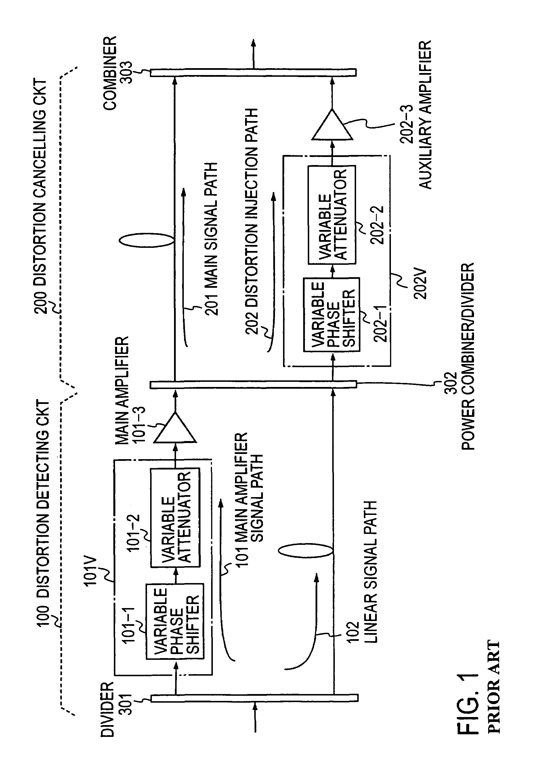
In practice, however, it is not easy to keep perfect balance of each of the distortion detecting circuit 100 and the distortion cancelling circuit 200.
Even if their initialization is perfect, extreme difficulty is encountered in stably maintaining them in an excellent state of balance for a long time because the amplifier characteristics vary with changes in the ambient temperature, the power-supply voltage, and so forth.
With such a configuration, it is impossible to perform simultaneous distortion cancellation, for example, in the 800 MHz and 1.5 GHz bands.
The vector adjusters cannot make optimum vector adjustment for the respective frequency bands.
The use of the feed-forward amplifier for each frequency band is disadvantageous in the overall size and power consumption of the system as compared with those in the case of using one feed-forward amplifier common to the respective frequency bands.

Method used


Image

  • Multi-band feed-forward amplifier and adjustment method therefor
  • Multi-band feed-forward amplifier and adjustment method therefor
  • Multi-band feed-forward amplifier and adjustment method therefor

Examples


embodiment 1

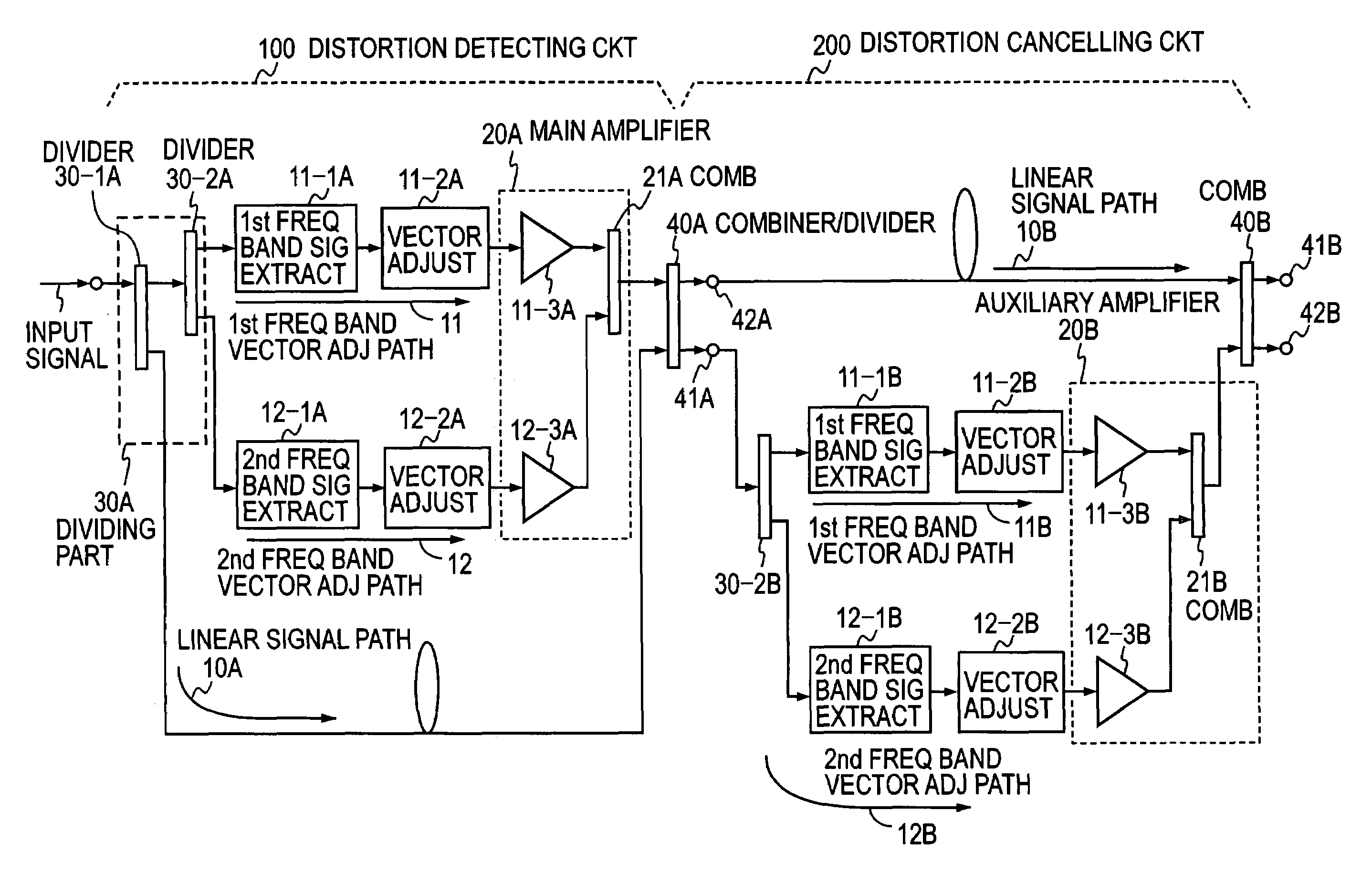
[0076]FIG. 8 illustrates in block form a first embodiment of the feed-forward amplifier according to the present invention. This embodiment uses, as the distortion detecting circuit 100, the multi-band signal processing circuit shown in FIG. 6, the respective parts being denoted by reference numerals added with a suffix “A.” Also this embodiment uses, as the distortion cancelling circuit 200, the multi-band signal processing circuit of FIG. 6, the respective parts being denoted by reference numerals being added with a suffix “B.” The following embodiments of the invention will be described as using two frequency bands for the brevity of description, but in general more than two frequency bands can be used as desired.

[0077]The combining part 40A of the multi-band signal processing circuit forming the distortion detecting circuit 100 is used also as the divider 30-1 (see FIG. 6) in the multi-band signal processing circuit forming the distortion cancelling circuit 200, and hence it fun...

embodiment 2

[0086]FIG. 10 illustrates in block form a second embodiment of the feed-forward amplifier according to the present invention. This embodiment uses, as the distortion cancelling circuit 200 in the FIG. 8 embodiment, the multi-band signal processing part shown in FIG. 7. The feed-forward amplifier of this embodiment also makes vector adjustment by use of the vector adjusters 11-2A, 11-2B and 12-2A, 12-2B for the respective frequency bands, and hence it permits compensation for distortion independently for each frequency band. With the vector adjustment paths sufficiently isolated from each other, the adjustment of the vector adjuster for one frequency band does not exert any influence on the vector adjustment of the vector adjuster for the other frequency band. Thus the vector adjusters for multiple frequency bands can be adjusted independently of each other. Simple addition of a required vector adjustment path provides flexibility to the addition of a desired frequency band in which ...

embodiment 3

[0088]FIG. 11 illustrates in block form a third embodiment of the feed-forward amplifier according to the present invention. In this embodiment the multi-band signal processing circuit depicted in FIG. 7 is used as the distortion detecting circuit 100 in the FIG. 8 embodiment. The feed-forward amplifier of this embodiment also makes vector adjustment by use of the vector adjusters 11-2A, 11-2B and 12-2A, 12-2B for the respective frequency bands, and hence it permits compensation for distortion independently for each frequency band.

[0089]Since the main amplifier 20A of the distortion detecting circuit 100 is formed by a single common amplifier 23A that simultaneously amplifies signals of multiple frequency bands as the common amplifier 23 in FIG. 7, it is possible to achieve simplification of the device configuration and power savings from reduction in the number of amplifiers used.


PUM


Abstract

A multi-band feed-forward amplifier is formed by: a dividing part for dividing and applying an input signal containing signals of multiple frequency bands to a linear signal path and N vector adjustment paths of a distortion detecting circuit; frequency band signal extractors provided in the N vector adjustment paths, respectively, for extracting signals of N frequency bands; N vector adjusters for adjusting the vectors of the output signals from the respective frequency band signal extractors; a main amplifier for amplifying the output signals from the N vector adjusters; a combining / dividing part for combining the amplified signals and the signal from the linear signal path of the distortion detecting circuit and for dividing and applying the combined output to a linear signal path and N distortion injection paths of a distortion cancelling circuit; frequency band signal extractors provided in the N distortion injection paths, respectively, for extracting the signals of the N frequency bands; vector adjusters for adjusting the vectors of signals separated into the N frequency bands; an auxiliary amplifying part for amplifying the vector-adjusted N signals; and a combining part for combining the amplified signals and the signal from the linear signal path of the distortion cancelling circuit.

Description

FIELD OF THE INVENTION[0001]The present invention relates to a multi-band feed-forward amplifier for collectively or simultaneously amplifying signals of multiple frequency bands and a method for adjustment of the feed-forward amplifier.DESCRIPTION OF THE PRIOR ART[0002]In FIG. 1 there is shown the basic configuration of a conventional feed-forward amplifier. The feed-forward amplifier comprises in principle two signal processing circuits, one of which is a distortion detecting circuit 100 and the other of which is a distortion cancelling circuit 200. The distortion detecting circuit 100 is made up of a main amplifier signal path 101 and a linear signal path 102. The distortion cancelling circuit 200 is made up of a main signal path 201 and a distortion injection path 202. The main amplifier signal path 101 (hereinafter referred to also as a vector adjustment path) is composed of a vector adjuster 101V formed by a cascade connection of a variable phase shifter 101-1 and a variable a...

Claims


Application Information

Patent Timeline
Patent Type & Authority Patents(United States)
IPC IPC(8): H03F1/00H03F1/32
CPCH03F1/3223H05B3/60
Inventor SUZUKI, YASUNORINARAHASHI, SHOICHI
Owner NTT DOCOMO INC
Learn More