Clasp for bracelet incorporating an antenna and bracelet including the same

a technology of bracelets and antennas, applied in protective materials, instruments, horology, etc., can solve the problems of poor quality of electric contact, complex plug-in solutions, and inconvenient tongue solutions, and achieve good electric cohesion and large surface area

Inactive Publication Date: 2006-10-24
TISSOT SA
View PDF6 Cites 5 Cited by
  • Summary
  • Abstract
  • Description
  • Claims
  • Application Information

AI Technical Summary

Benefits of technology

[0008]It is thus a general object of the present invention to propose a solution, on the one hand, for ensuring an adequate electrical connection between the two antenna elements housed in the wristband strands and which also, on the other hand, enables bulkiness to be reduced around the clasp.
[0012]This solution offers the advantage of assuring a very broad electric contact surface between the two detachable parts of the clasp once locked. In fact, the two plates, thus arranged, ensure by their relatively large surface area, good electric cohesion between the two detachable parts of the clasp. On the other hand, the third clasp element, when it is locked onto the second clasp element, exerts a pressure or compression force holding the plate of the first clasp element in tight contact with the plate of the second clasp element.
[0013]Preferably, the first plate is provided with a least one fixing orifice passing through the thickness of the first plate and the holding device includes at least one fixing stud arranged substantially perpendicularly to the second plate and one end of which is arranged to lock onto the third clasp element, the fixing orifice and the fixing stud being arranged such that, when the first and second plates are superposed, the fixing stud passes through the fixing orifice. This variant ensures a proper mechanical grip for the clasp.

Problems solved by technology

The buckle with a tongue solution is not suitable in practice because of the poor quality of the electric contact, and the plug-in type solution is complex from a mechanical point of view.
This type of solution thus has a drawback insofar as the exposed parts of the antenna elements can quickly become oxidized and thus cause the quality of the electric contact to deteriorate.
From an aesthetic point of view, this type of solution is also not very desirable.
Another drawback of these solutions lies in the relatively large thickness of the wristband around the fastening device, the two strands of the wristband being superposed there.

Method used


Image

  • Clasp for bracelet incorporating an antenna and bracelet including the same
  • Clasp for bracelet incorporating an antenna and bracelet including the same
  • Clasp for bracelet incorporating an antenna and bracelet including the same

Examples


Embodiment Construction

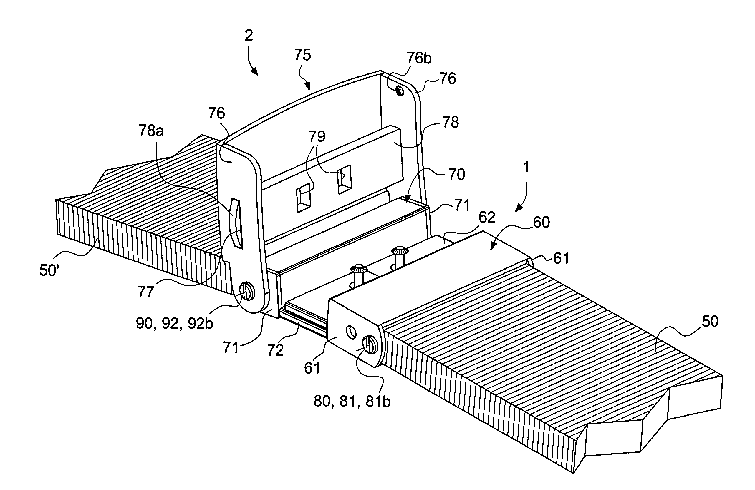
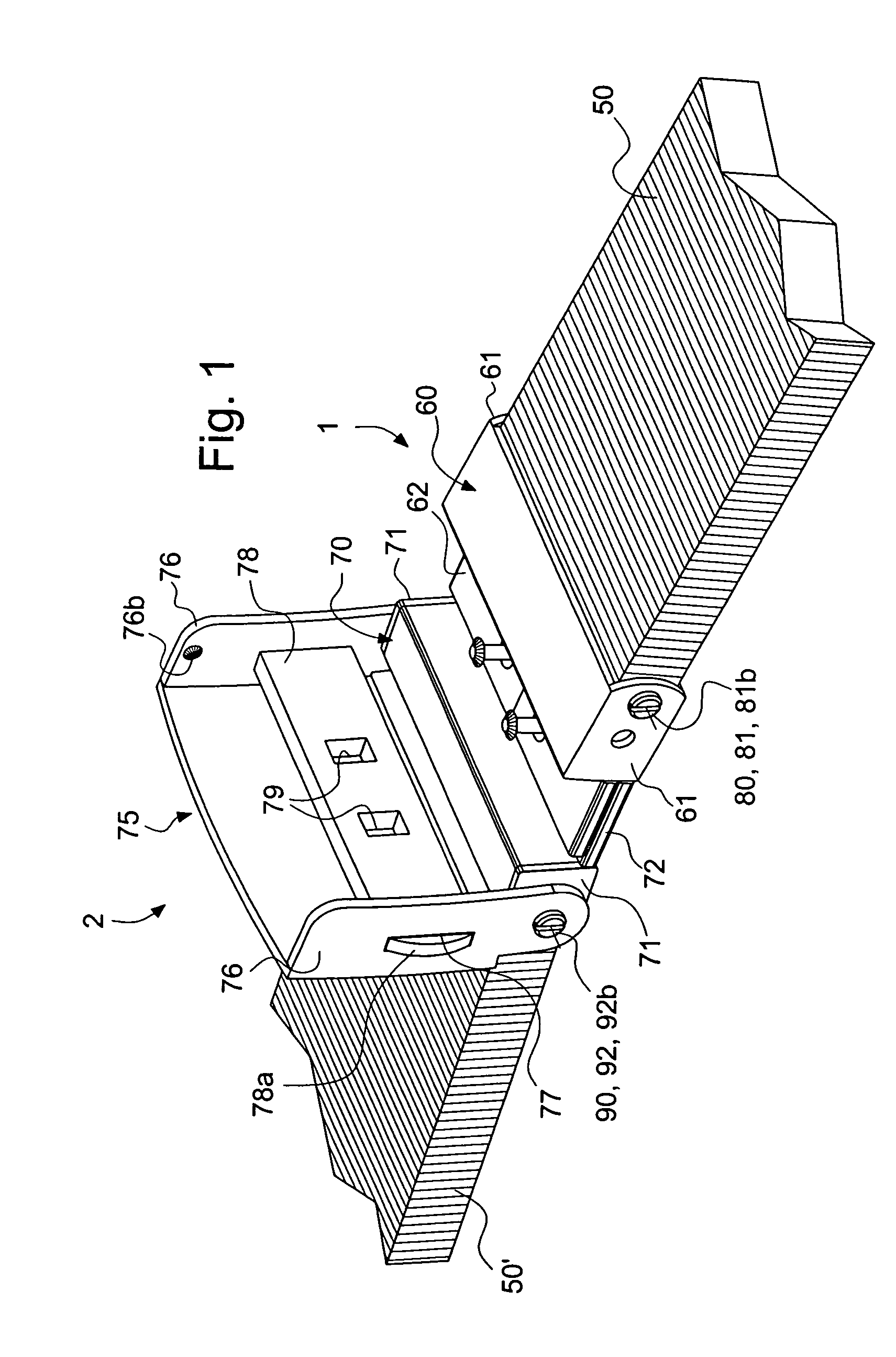
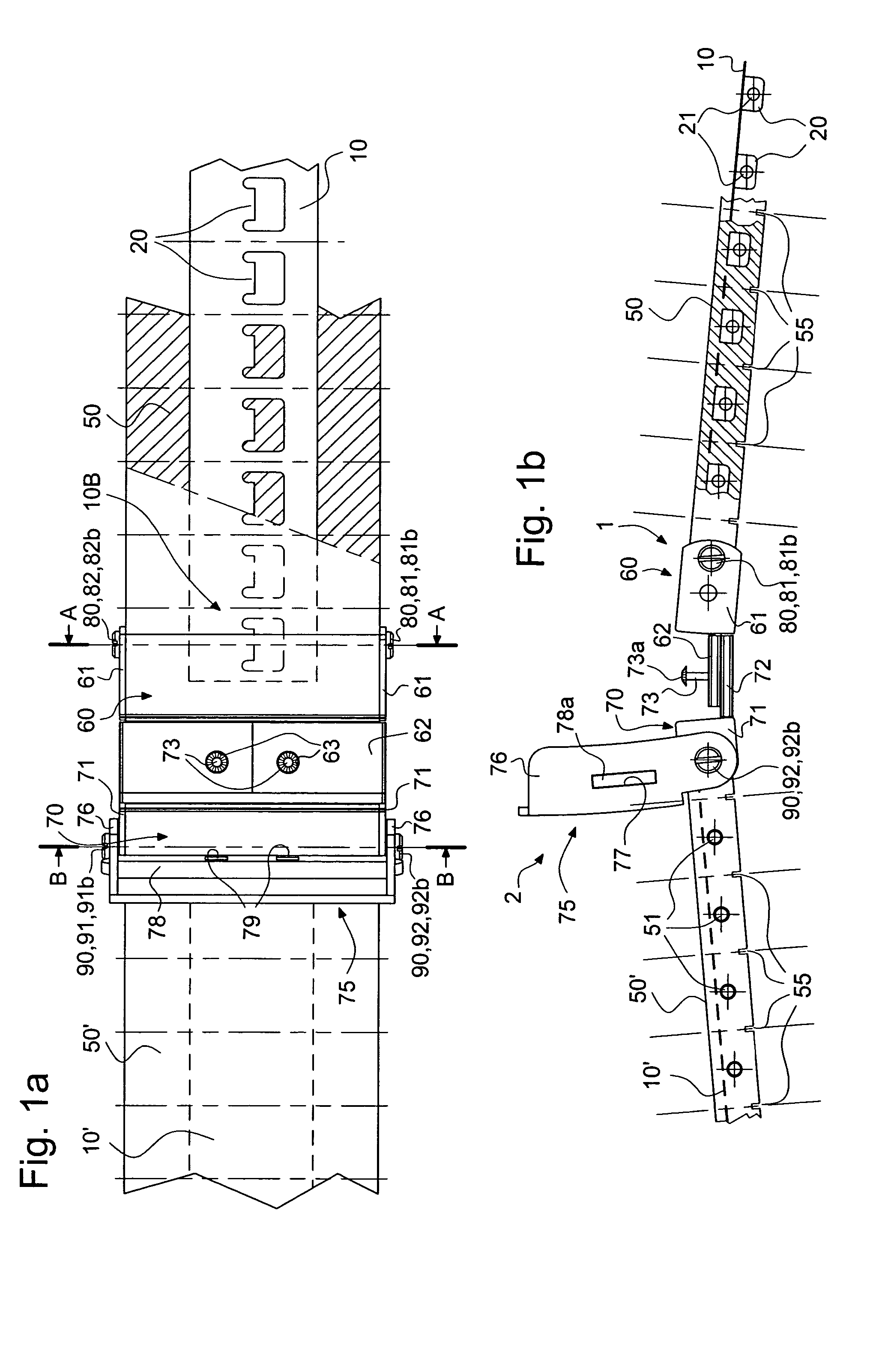
[0024]Within the scope of the non-limiting example that will be given in the following description, it will be noted now that the wristband includes two identical wristband strands each including the same antenna element, these two strands being attached to each other by the clasp, so that the two antenna elements are electrically connected to each other so as to form a loop antenna around the wrist. This type of antenna configuration in a wristband is well known and its operating principle will not therefore be explained here. Fuller information on this point can be found in the documents cited in the preamble.

[0025]FIGS. 1, 1a and 1b show respectively a perspective view, a plan view on the side of the external wristband face (by definition the “external face” is defined as the face oriented towards the outside of the wrist when the wristband is being worn, as opposed to the “internal face” which designates the face of the wristband which is in contact with the wrist when the wrist...


PUM


Abstract

There is disclosed a clasp for electrically connecting first (10) and second (10′) antenna elements respectively housed in first (50) and second (50′) strands of a wristband of a portable electronic instrument, this clasp including two parts (1, 2) able to be detached from each other, each electrically connected to one of the antenna elements, and able to be mechanically locked onto each other in order to establish an electric contact between the antenna elements. The first detachable part includes a first clasp element (60) including a first plate (62) extending into the extension of the first wristband strand. The second detachable part includes a second clasp element (70) including a second plate (72) extending into the extension of the second wristband strand and a holding device (73). The second detachable part further includes a third clasp element (75) rotatably mounted on the second clasp element (70) and arranged to lock onto the holding device of the second clasp element. The clasp elements are arranged such that, during locking, the first plate is superposed onto the second plate and the third clasp element sandwiches the first plate against the second plate when it is locked onto the holding device.

Description

[0001]This application claims priority from European Patent Application No 03016357.0 filed on Jul. 18, 2003, the entire disclosure of which is incorporated herein by reference.FIELD OF THE INVENTION[0002]The present invention generally concerns a clasp for electrically connecting first and second antenna elements housed respectively in first and second strands of a wristband of a portable electronic instrument, this clasp including first and second parts that can be detached from each other, respectively electrically connected to the first and second antenna elements, and able to be mechanically locked onto each other to establish an electric contact between the first and second antenna elements. The present invention also concerns a wristband including such a clasp.BACKGROUND TO THE INVENTION[0003]Clasps answering the general definition given hereinbefore are already known. European Patent No. 0 125 930 discloses, for example, such a clasp for ensuring the electrical connection of...

Claims


Application Information

Patent Timeline
Patent Type & Authority Patents(United States)
IPC IPC(8): H01Q1/12A44C5/18A44B11/25A44C5/00A44C5/20G04G21/04G04G99/00H01Q1/24H01Q1/27H01Q1/38H01Q1/40H01Q1/44
CPCA44B11/2588A44C5/2071H01Q1/243H01Q1/273H01Q1/38H01Q1/40
Inventor CLERC, NICOLASOIAN, NICOLASAPOTHELOZ, DAVID
Owner TISSOT SA
Why Eureka
Try Eureka