Radio base station/radio base station controller equipped with inactivity timer, mobile station, and state control method

a radio base station and controller technology, applied in multiplex communication, wireless commuication services, instruments, etc., can solve the problems of reducing the use efficiency increasing the connection/disconnection of the radio channel, and so as to reduce the unused time of the communication channel, increase the communication opportunity of each mobile station, and increase the channel use efficiency

Inactive Publication Date: 2006-10-24
HITACHI LTD
View PDF3 Cites 39 Cited by
  • Summary
  • Abstract
  • Description
  • Claims
  • Application Information

AI Technical Summary

Benefits of technology

[0010]An object of the present invention is to decrease an unused time of a communication channel in a non-communication time and to raise channel use efficiency by changing an inactivity timer value according to various states such as the type of data. By this, there also occurs an opportunity of raising the communication opportunity of each mobile station. Besides, another object of the present invention decreases the number of connection / disconnection processings of a radio channel by suitable setting of an inactivity timer for each application.
[0011]In the present invention, a set value of an inactivity timer is changed especially by the type of data to be transmitted and received. Specifically, an inactivity timer value of a mobile station for intermittently transmitting and receiving data having a small size and taking a short communication time is set to a short time, and an inactivity timer value of a mobile station for transmitting and receiving data having a large size, taking a considerable communication time, and divided into packets is set to a long time. Since a time when a mobile station occupies a radio channel can be decreased on average by that, it is possible to give an opportunity of using the radio channel to many mobile stations in a cell.

Problems solved by technology

Thus, in the case where the set value of the inactivity timer is made the fixed value, unless the inactivity timer value is suitably set according to a traffic amount in such a manner that it is set to be short when data such as E-mail having a small size and taking a short communication time is intermittently transmitted and received, and it is set to be long when data such as stream data having a large size and taking a considerable communication time is divided into packets and is transmitted and received, there is a problem that surplus processing due to connection / disconnection of the radio channel is increased, and the use efficiency of the radio channel is lowered.
However, as long as the fixed value of the inactivity timer is used, the above problem always remains.

Method used


Image

  • Radio base station/radio base station controller equipped with inactivity timer, mobile station, and state control method
  • Radio base station/radio base station controller equipped with inactivity timer, mobile station, and state control method
  • Radio base station/radio base station controller equipped with inactivity timer, mobile station, and state control method

Examples


first embodiment

2. Setting of an Inactivity Timer According to a Header of a Transmission or Reception Packet

2-1. Setting of an Inactivity Timer According to an Application Type (Data Type)

[0065]Hereinafter, an embodiment of the present invention will be described with reference to the drawings.

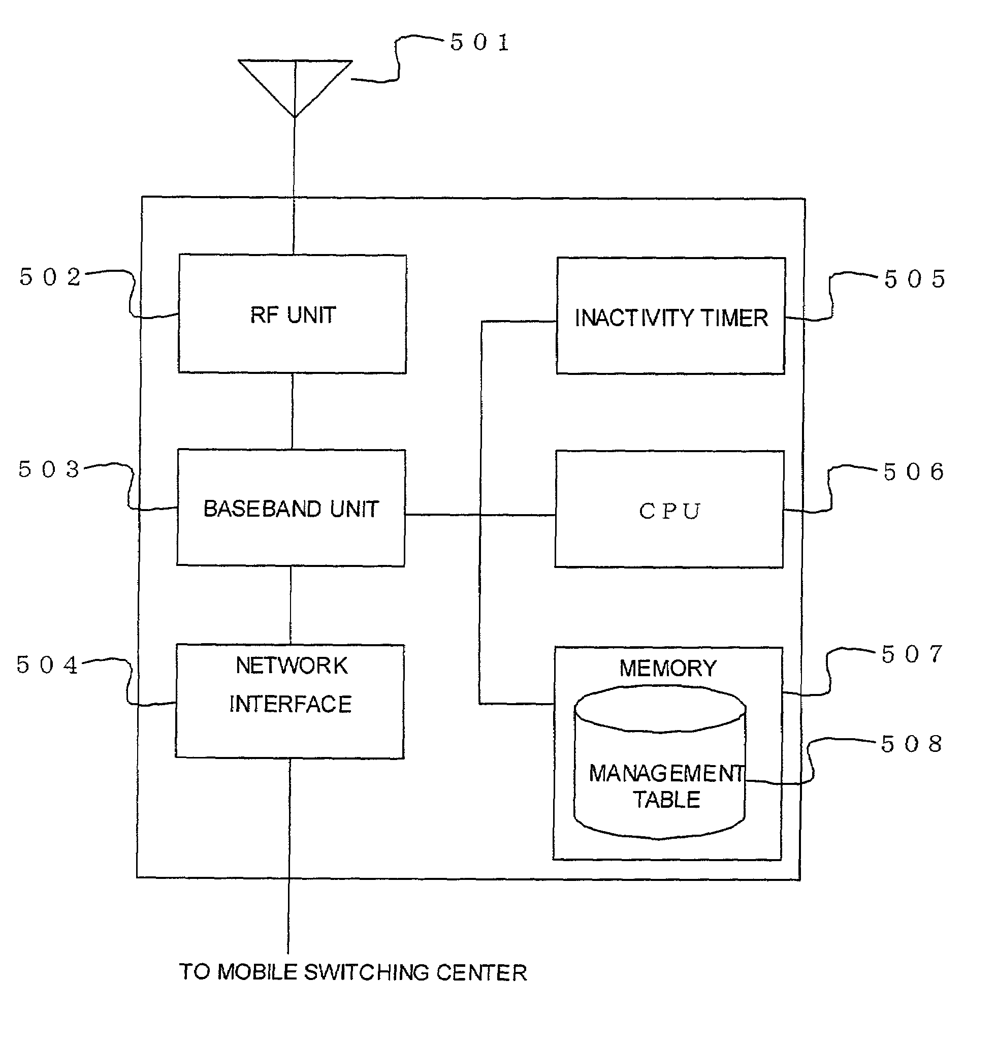
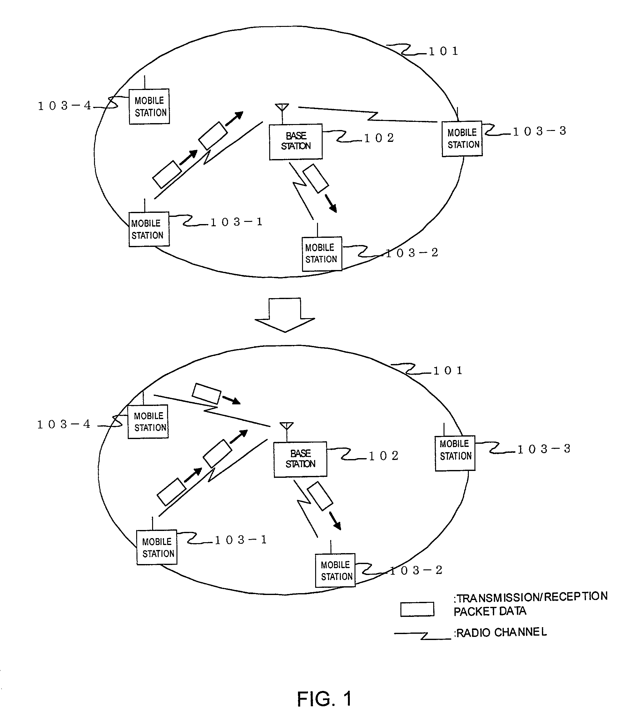
[0066]FIG. 4 is a view showing a network architecture of a radio communication system in the present invention. A mobile switching center 405 has a switching function in mutual communication of a mobile station 410, and a base station 408 controls a communication channel between the mobile station 410 and the mobile switching center 405 and controls a radio channel 409 with the mobile station 410. An HLR (Home Location Register) 406 in the mobile switching center is an apparatus for storing subscriber data at the time of contract of a mobile station and carrying out position management of the mobile station, and a data base 407 is an apparatus for storing various pieces of information relating to the mobile ...

second embodiment

3. Setting of an Inactivity Timer by a TCP / UDP Header

[0098]A method in which an application is judged from a port number in a TCP / UDP header and an inactivity timer value is set, will be described below.

[0099]Both the TCP (Transmission Control Protocol) and the UDP (User Datagram Protocol) are upper protocols of the IP (Internet Protocol), and under the environment where packet data communication is carried out using the TCP / IP protocol, data is added with the TCP header or the UDP header and is transmitted. The port number is used for identifying programs carrying out communication in the same computer. This port number includes a well-known port number, and in application protocols, such as http or ftp, which are used very widely, a port number to be used is determined in advance.

[0100]FIG. 17 is a header format of the TCP. As described above, a TCP header 1702 is added to a TCP data field 1701, and a port number is indicated in a destination port 1703 assigned to 17-th to 32-th b...


PUM


Abstract

In data communication using radio communication, an inactivity timer value is changed according to various states, so that an unused time of a communication channel in a non-communication time is decreased, and channel use efficiency is raised. A unit for judging an application of packet data to be transmitted and received by a radio base station 408 / a radio base station controller 405 is provided, or an inactivity timer value is set through a port number in TCP / UDP header and a traffic pattern and according to a communication content, and the set inactivity timer value is used to control a change from a connected state to a dormant state.

Description

BACKGROUND OF THE INVENTION[0001]1. Field of the Invention[0002]The present invention relates to a radio base station / radio base station controller (hereinafter referred to as a base station) for carrying out radio communication with a mobile station, a mobile station, and a state control method of those, and particularly to a base station, a mobile station, and a state control method of those, in which setting of an inactivity timer value is dynamically changed according to a use state to decrease an unused time of a radio channel in a non-communication time in which transmission / reception of data is not carried out and to improve the use efficiency of the radio channel. Incidentally, the inactivity timer value is, as described below, a value for determining the timing when a radio channel disconnection processing for changing a connected state to a dormant state is started (see a document “cdma 2000 High Rate Packet Data Air Interface Specification, 3GPP2 C. S0024 Version 2.0, Oct...

Claims


Application Information

Patent Timeline
Patent Type & Authority Patents(United States)
IPC IPC(8): H04J3/17H04B7/00H04M3/00H04W76/02H04W76/04H04W88/14
CPCH04W76/068H04W76/38
Inventor SUZUKI, MASAYASUYOSHIMURA, MANABUMAZAWA, SHIROAOE, HIDEONAKAGOSHI, ARATA
Owner HITACHI LTD
Why Eureka
Try Eureka