
Method for transmitting at least one first and one second data signal in polarization division multiplex in an optical transmission system

Inactive Publication Date: 2006-10-24
XIEON NETWORKS SARL
View PDF2 Cites 13 Cited by
  • Summary
  • Abstract
  • Description
  • Claims
  • Application Information

AI Technical Summary

Benefits of technology

[0009]A further advantage of the present invention can be seen in the fact that, to distinguish between the first and second electrical signals, at least one pilot tone signal is superimposed on the first and / or the second carrier signal at the transmitting end. Advantageously, a pilot tone having a specified frequency, with the aid of which, after the first and second modulated signals have been separated with the aid of the polarization splitter and converted into a first and second electrical signal at the transmitting end, an unambiguous identification of the first and second electrical signals as such becomes possible, is superimposed on the first and / or second modulated signal. As an alternative, the first and second transmission bit rate can be selected to be different rates for distinguishing the first and second electrical signals. In an alternative embodiment, the respective electrical signal is advantageously identified via its individual transmission bit rate.
[0010]Additional features and advantages of the present invention are described in, and will be apparent from, the following

Problems solved by technology

One of the essential problems in transmitting optical data signals in polarization division multiplex is separating the two orthogonally polarized modulated signals precisely out of the polarization division multiplex signal.

Method used


Image

  • Method for transmitting at least one first and one second data signal in polarization division multiplex in an optical transmission system
  • Method for transmitting at least one first and one second data signal in polarization division multiplex in an optical transmission system
  • Method for transmitting at least one first and one second data signal in polarization division multiplex in an optical transmission system

Examples


Embodiment Construction

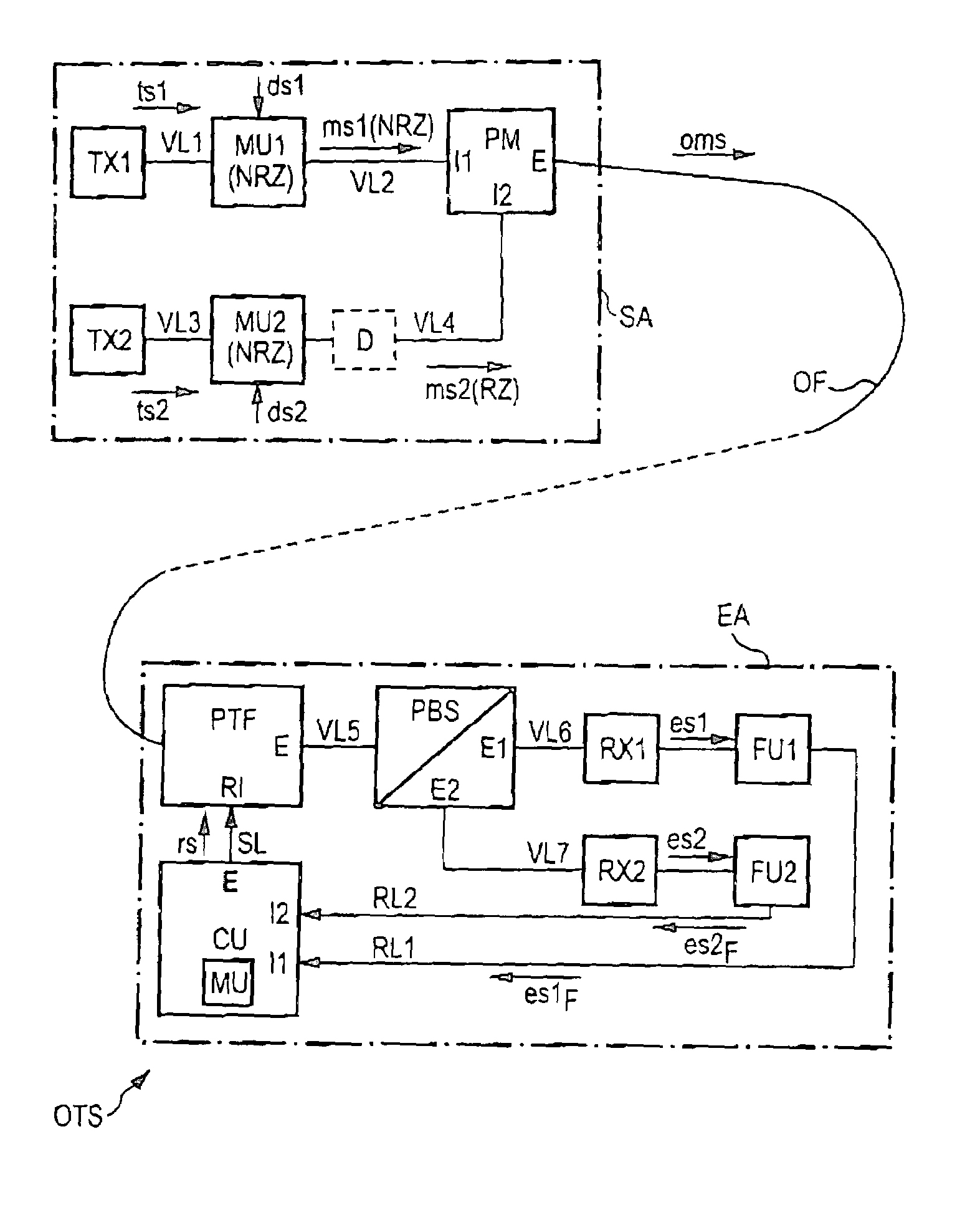
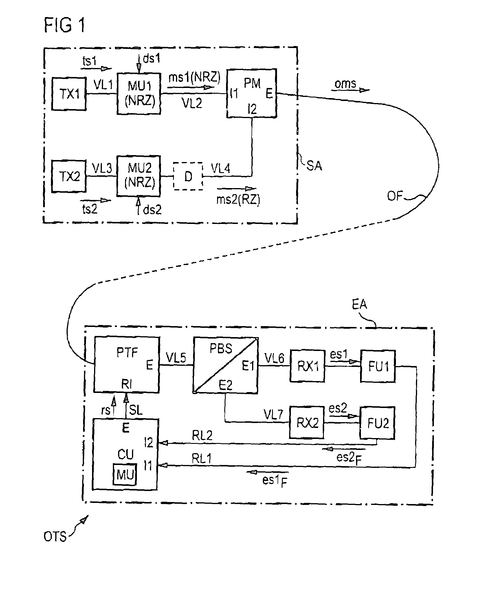
[0014]FIG. 1 diagrammatically shows, by way of example, an optical transmission system OTS which exhibits a transmitting arrangement SA and a receiving arrangement EA connected via an optical transmission link OF. In the transmitting arrangement SA, a first and second signal generating unit TX1, TX2, a first and second modulator unit MU1, MU2, a delay element D and a polarization multiplexer PM are provided, by way of example. The receiving arrangement EA includes a polarization control element PTF, a polarization splitter PBS, a first and second optoelectrical transducer RX1, RX2, a first and second filter unit FU1, FU2 and a control unit CU.

[0015]The first signal generating unit TX1 of the transmitting arrangement SA is connected via a first connecting line VL1 to the first modulator unit MU1 which is connected to the first input I1 of the polarization multiplexer PM via a second connecting line VL2. The second signal generating unit TX2 is connected via a third connecting line VL...


PUM


Abstract

In an optical transmission system, a first modulated signal with a first transmission bit rate is generated at the transmitting end by modulating a first carrier signal with the first data signal, using a nonreturn to zero coding, and a second modulated signal with a second transmission bit rate is generated by modulating a second carrier signal with the second data signal, using a return to zero coding. The first and second modulated signal are polarized orthogonally with respect to one another and combined to form an optical multiplex signal and transmitted. At the receiving end, the optical multiplex signal is conducted via a polarization control element to a polarization splitter which splits the optical multiplex signal into the first and second modulated signal. The first modulated signal is converted into a first electrical signal and the second modulated signal is converted into a second electrical signal, the spectral component of the first and / or the second electrical signal is determined at the frequency corresponding to the first transmission rate and from this at least one control signal is derived for controlling the polarization control element.

Description

BACKGROUND OF THE INVENTION[0001]The present invention relates to a method for transmitting at least one first and one second data signal in polarization division multiplex in an optical transmission system which includes a transmitting arrangement and a receiving arrangement which are connected to one another via at least one optical fiber link section.[0002]In optical transmission systems, the transmission capacity of existing optical transmission systems can be extended by transmitting the optical data signals in polarization division multiplex. To transmit optical data signals in polarization division multiplex, in each case two carrier signals which are respectively modulated with a data signal are generated in at least one transmitting arrangement with the same wavelength. The first and second modulated signals exhibit a mutually orthogonal polarization in this case. The mutually orthogonally polarized modulated signals are combined to form an optical polarization division mul...

Claims


Application Information

Patent Timeline
IPC IPC(8): H04J14/06H04B10/00H04B10/532
CPCH04B10/532H04J14/06
Inventor GLINGENER, CHRISTOPH
Owner XIEON NETWORKS SARL
Learn More