
Method and apparatus for multiplexing in a wireless communication infrastructure

Inactive Publication Date: 2006-10-24
NEXTG NETWORKS INC
View PDF82 Cites 193 Cited by
  • Summary
  • Abstract
  • Description
  • Claims
  • Application Information

AI Technical Summary

Benefits of technology

[0035]In another embodiment of the present invention, a network includes a plurality of antennas optically coupled over the network to a plurality of base stations, the base stations configured to provide cellular transmission. A plurality of links couple the plurality of antennas and the plurality of base stations. At least one link of the p

Problems solved by technology

In densely populated urban areas, the capacity of a conventional system is limited by the relatively small number of channels available in each cell.
Moreover, the coverage of urban cellular phone systems is limited by blockage, attenuation and shadowing of the RF signals by high rises and other structures.
This can also be a problem with respect to suburban office buildings and complexes.
While such “microcell” systems are a viable solution to capacity and coverage problems, it can be difficult to find space at a reasonable cost to install conventional base station equipment in each microcell, especially in densely populated urban areas.
Furthermore, maintaining a large number of base stations spread throughout a densely populated urban area can be time consuming and uneconomical.

Method used


Image

  • Method and apparatus for multiplexing in a wireless communication infrastructure
  • Method and apparatus for multiplexing in a wireless communication infrastructure
  • Method and apparatus for multiplexing in a wireless communication infrastructure

Examples


Embodiment Construction

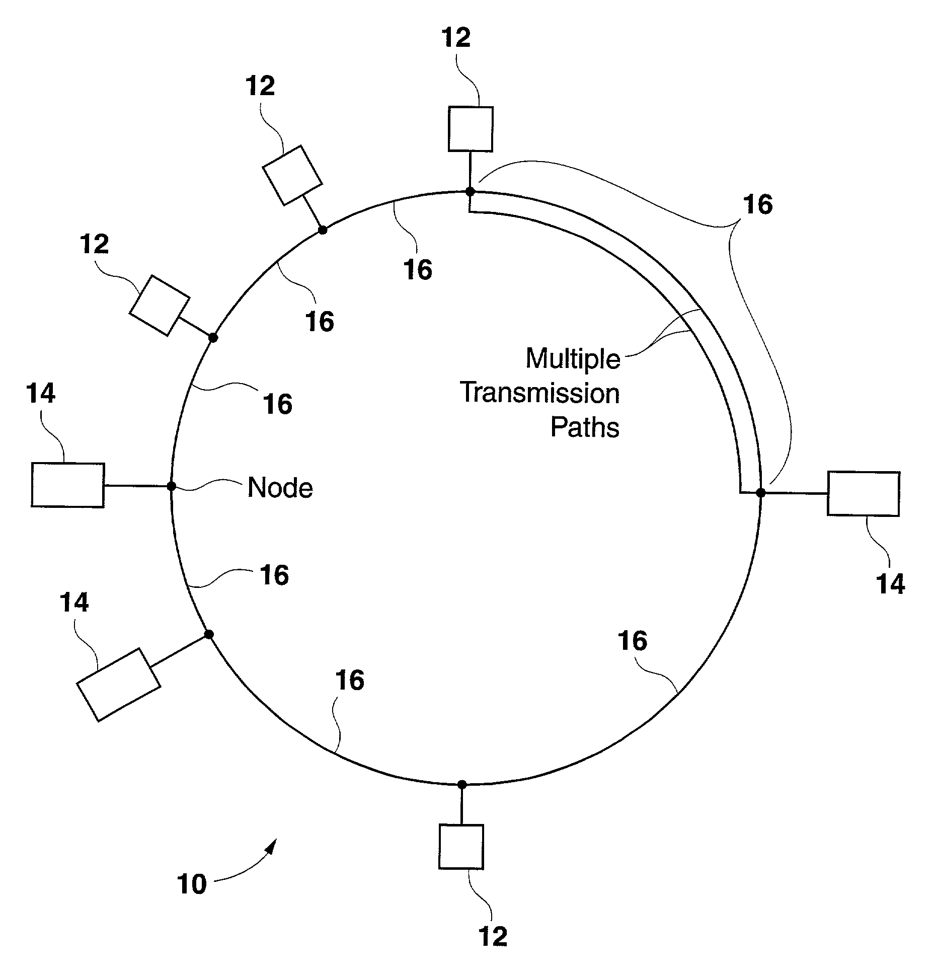
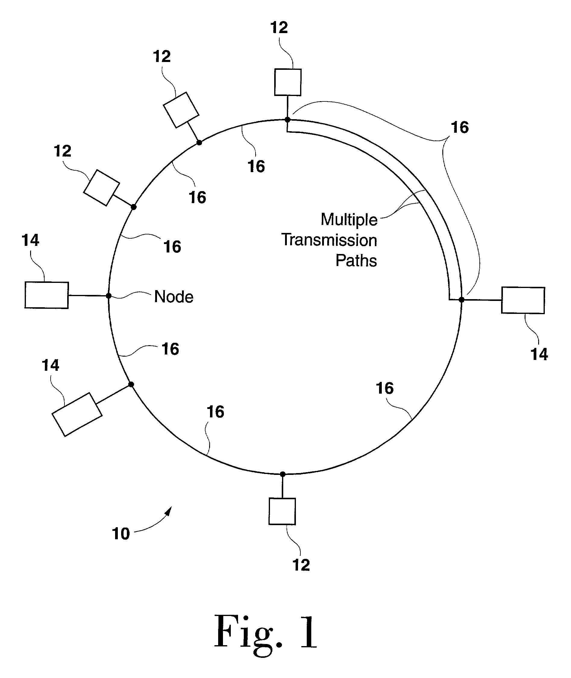
[0063]Referring to FIG. 1, one embodiment of the present invention is a network 10 that includes a plurality of antennas 12 that are optically coupled over network 10 to a plurality of base stations 14. Base stations 14 are configured to provide wireless cellular transmission. A plurality of links 16 couple the plurality of antennas 12 and the plurality of base stations 14. At least one link 18 of the plurality of links 16 provides multiple transmission paths between at least a portion of the plurality of base stations 14 with at least a portion of the plurality of antennas 12. In one embodiment, the plurality of antennas 12 and base stations 14 are coupled using RF links to form a network 10. By remotely locating the antenna 12 units from the base stations using such a network 10, numerous advantages are realized.

[0064]The plurality of links 16 can be configured to provide multiple transmission paths by frequency division multiplexing (FDM), time division multiplexing (TDM), and th...


PUM


Abstract

A network is provided that includes a plurality of antennas coupled over the network to a plurality of base stations. The network can be optical or constructed with RF microwave links. The base stations are configured to provide cellular transmission. A plurality of links couple the plurality of antennas and the plurality of base stations. At least one link of the plurality of links provides multiple transmission paths between at least a portion of the base stations with at least a portion of the antennas. In one implementation, at least one link of the plurality of links is shared by at least two cellular operators on different transmission paths. In another implementation, at least a portion of the plurality of base stations are in a common location and at least a portion of the antennas are geographically disbursed.

Description

CROSS-REFERENCE TO RELATED APPLICATIONS[0001]This application claims the benefit of U.S. Provisional Application No.: 60 / 296,781 filed Jun. 8, 2001 and U.S. Provisional Application No.: 60 / 313,360 filed Aug. 17,2001. This application is also a continuation-in-part of U.S. patent application Ser. No. 10 / 012,208, filed Nov. 5, 2001, published as U.S. Pub. No. 2002 / 0186674 on Dec. 12, 2002, and a continuation-in-part of U.S. patent application Ser. No. 10 / 012,246, filed Nov. 5, 2001, published as U.S. Pub. No. 2002 / 0186436 on Dec. 12, 2002.BACKGROUND OF THE INVENTION[0002]1. Field of the Invention[0003]This invention relates generally to cellular mobile telecommunication systems, and more particularly to a shared network to distribute base station antenna points and the associated base station transceiver hardware.[0004]2. Description of Related Art[0005]A conventional cellular telecommunications system has a fixed number of frequency channel sets distributed among base stations that s...

Claims


Application Information

Patent Timeline
IPC IPC(8): H04B10/00H04B10/12H04B13/00H04J14/02H04W16/24H04W88/08
CPCH04B10/25755H04B13/00H04J14/02H04Q11/0067H04W88/085H04Q2011/0092H04W16/24
Inventor MANI, SANJAYCUTRER, DAVID
Owner NEXTG NETWORKS INC
Learn More