
Method of permanently joining first and second metallic components

a technology of metallic components and permanent joining, which is applied in the direction of manufacturing tools, couplings, transportation and packaging, etc., can solve the problems of relatively heavy steel alloys and relatively difficult permanent joining of such structural components using traditional welding techniques, and achieve the effect of facilitating the performance of the magnetic pulse welding process

Inactive Publication Date: 2006-10-31
METALSA SA DE CV
View PDF27 Cites 36 Cited by
  • Summary
  • Abstract
  • Description
  • Claims
  • Application Information

AI Technical Summary

Benefits of technology

"This patent is about a better way to join two metal parts together using a process called magnetic pulse welding. The method involves putting the two parts in a specific position and using a special tool to create a strong connection between them. The technique helps to align the parts and ensures a strong and durable connection. This method can be used in the assembly of vehicles and other structures, making it easier to join metal parts together."

Problems solved by technology

Unfortunately, steel alloys are also relatively heavy materials.
However, it has been found to be relatively difficult to permanently join such structural components using traditional welding techniques.

Method used


Image

  • Method of permanently joining first and second metallic components
  • Method of permanently joining first and second metallic components
  • Method of permanently joining first and second metallic components

Examples


Embodiment Construction

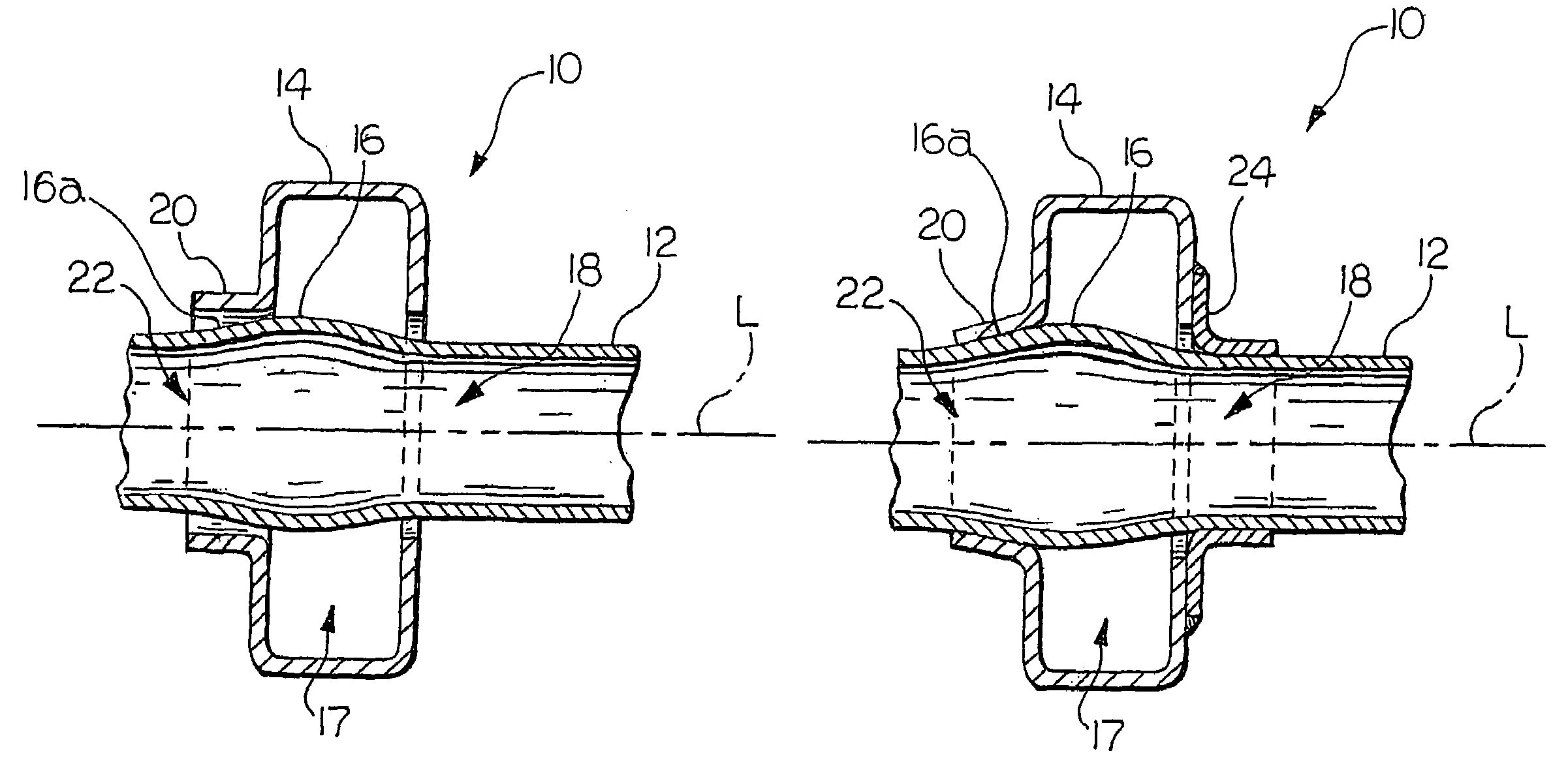
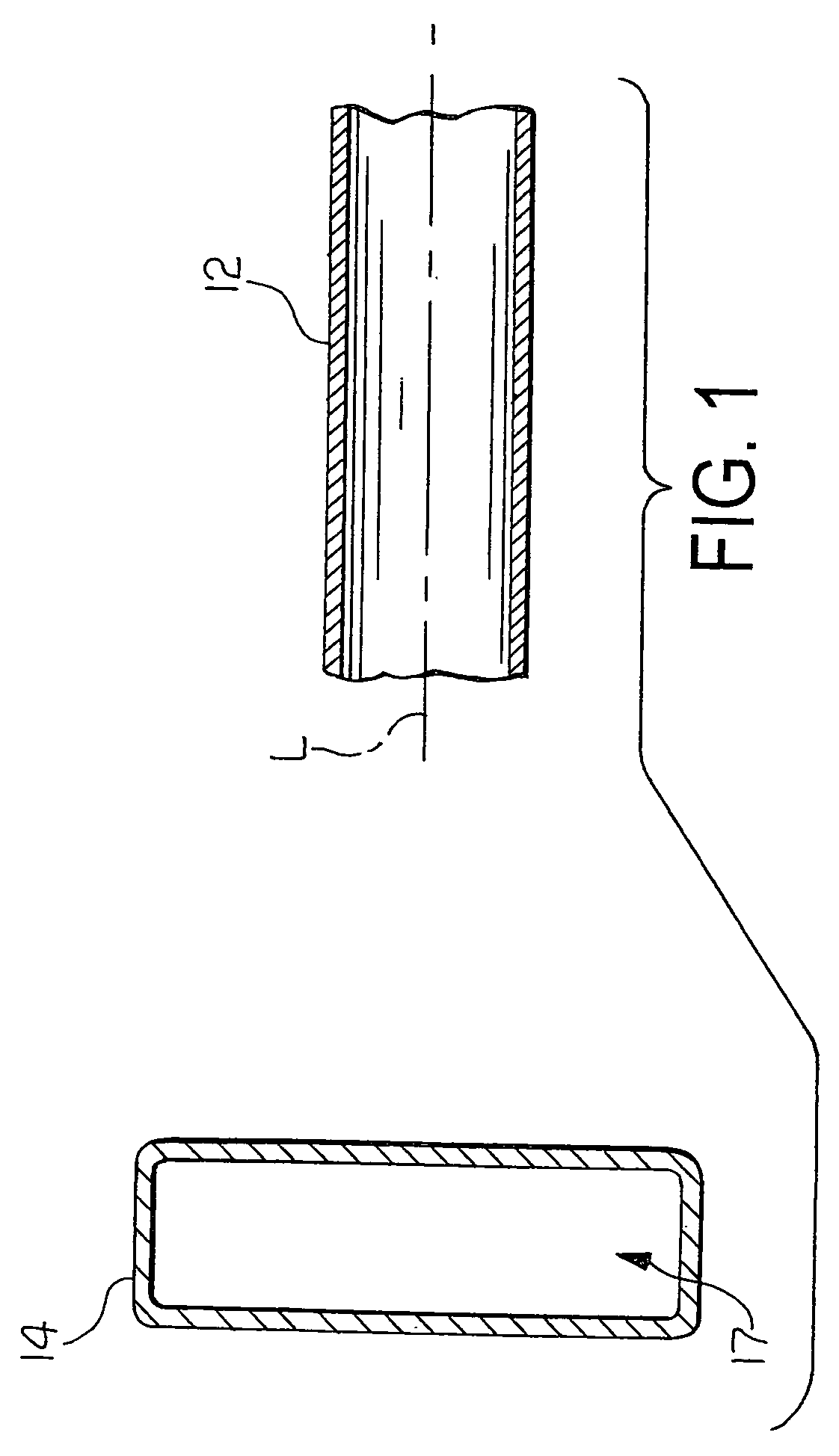
[0015]Referring now to the drawings, there is illustrated in FIG. 1 first and second metallic components 12 and 14, respectively, that are shown prior to being permanently joined in accordance with the method of this invention. The first and second metallic components 12 and 14 can, for example, be embodied as a cross member 12 and a side rail 14 or other metallic structural components for use in a vehicular body and frame assembly. Such vehicular body and frame assemblies are, of themselves, conventional in the art, and the illustrated cross member 12 and side rail 14 are intended merely to illustrate one environment in which this invention may be used. Thus, the scope of this invention is not intended to be limited for use with vehicular body and frame assemblies. On the contrary, as will become apparent below, this invention may be used in any desired environment for the purposes described below.

[0016]The cross member 12 can be embodied as an elongated structural component that i...


PUM

PropertyMeasurementUnit
angleaaaaaaaaaa
angleaaaaaaaaaa
angleaaaaaaaaaa

Abstract

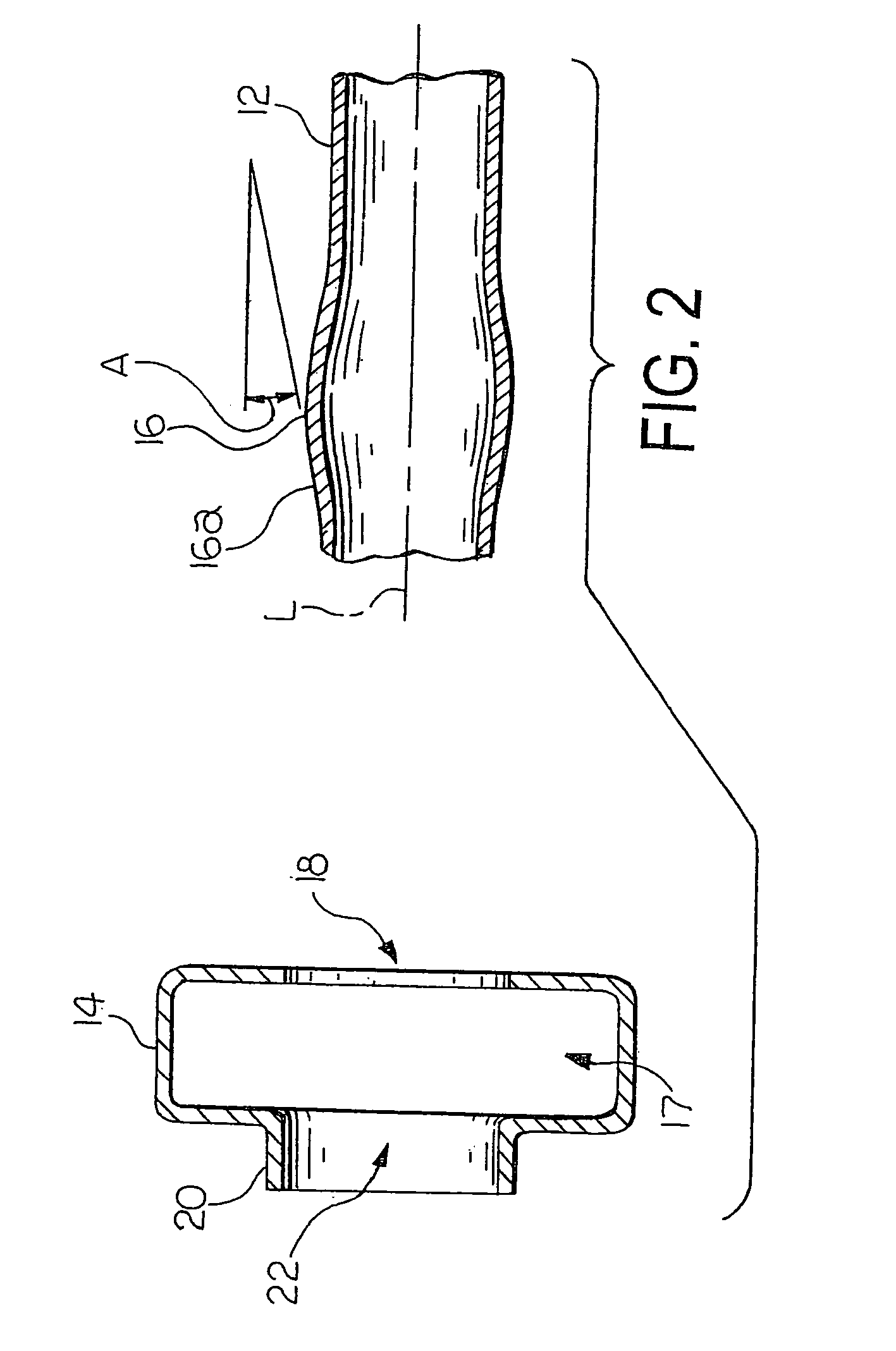
A pair of metallic components, such as a pair of metallic structural components for a vehicular body and frame assembly, are permanently joined using a magnetic pulse welding process. Initially, a first metallic component is provided having a first aperture that is formed through a first side and a second aperture having a hollow cylindrical flange portion that is formed through a second side. A second metallic component is provided having a surface that extends at an angle relative to the flange portion. The angled surface may be provided in the form of either an enlarged region or a reduced region on the second metallic component. The first and second metallic components are arranged such that the flange portion of the first metallic component overlaps the surface of the second metallic component. A magnetic pulse welding process is performed to cause the flange portion of the first metallic component and the angled surface of the second metallic component to engage one another and become permanently joined.

Description

BACKGROUND OF THE INVENTION[0001]This invention relates in general to methods for forming joints between metallic components, such as a joint between a pair of metallic structural components for use in a vehicular body and frame assembly. In particular, this invention relates to an improved method for permanently joining such a pair of metallic structural components using magnetic pulse welding techniques.[0002]Many land vehicles in common use, such as automobiles, vans, and trucks, include a body and frame assembly that is supported upon a plurality of ground-engaging wheels by a resilient suspension system. The structures of known body and frame assemblies can be divided into two general categories, namely, separate and unitized. In a typical separate body and frame assembly, the structural components of the body portion and the frame portion of the vehicle are separate and independent from one another. When assembled, the frame portion of the assembly is resiliently supported upo...

Claims


Application Information

Patent Timeline
Patent Type & Authority Patents(United States)
IPC IPC(8): B23P11/00B21D26/14B21D39/00B21D53/88B23P17/00B23K31/00
CPCB23K9/0288B23K28/02Y10T29/49908Y10T403/49Y10T29/49622Y10T29/49913Y10T29/49803Y10T29/49915Y10T403/4991Y10T403/4966
Inventor KIEHL, MARK W.
Owner METALSA SA DE CV
Learn More