Welding head for magnetic pulse welding of tubular profiles to a cylindrical inner member

a technology of magnetic pulse welding and tubular profile, which is applied in the direction of non-electric welding apparatus, manufacturing tools, other domestic objects, etc., can solve the problems of inability to weld closed tubular structures, imposed significant restrictions in application, and the mpw process may require a much higher repulsion for

Inactive Publication Date: 2017-09-21
VALMET AB
View PDF5 Cites 8 Cited by
  • Summary
  • Abstract
  • Description
  • Claims
  • Application Information

AI Technical Summary

Benefits of technology

[0026]What is needed is a MPW head that could be opened and closed quickly allowing loading and unloading of work pieces without having to pull out the weld head over the entire length of the work piece. Further, the problem with arcing should be avoided in contact surfaces extending service life of the weld head and thus the economical feasibility of the process. Yet another problem is to be able to weld tubular elements in designs having several tubular elements located close to one another.
[0027]It is an object of the present invention to prevent the problems in existing solutions.

Problems solved by technology

However, the MPW process may require a much higher repulsion force to generate sufficient velocity for bonding.
The welded assembly could only be removed axially from the closed coil of the welding head, which meant that welding of closed tubular structures was impossible, i.e. structures similar to toroids and similar closed tubular structures.
The closed coil design has imposed significant restrictions in application areas for the MPW technology.
In some applications the shape of hydro formed tubes are quite complex, preventing a physical removal of the welding head after welding.
However, if the electric current for exciting the coils is passed via such conducting surfaces they will be exposed to excessive wear and will be destroyed during operation due to arcing of electrical current.
However, this design also does not utilize a magnetic field in the volume encircled by the coil inner surface, where the magnetic field is most intensified.
The problem with arcing in the connecting surfaces of this connecting pin will still create problems, and coils could not be controlled individually.
Here are the two halves also totally encircling the welding position which makes it impossible to use in designs having neighboring tubular elements close to the welding position.
Yet another problem is to be able to weld tubular elements in designs having several tubular elements located close to one another.

Method used


Image

  • Welding head for magnetic pulse welding of tubular profiles to a cylindrical inner member
  • Welding head for magnetic pulse welding of tubular profiles to a cylindrical inner member
  • Welding head for magnetic pulse welding of tubular profiles to a cylindrical inner member

Examples


Embodiment Construction

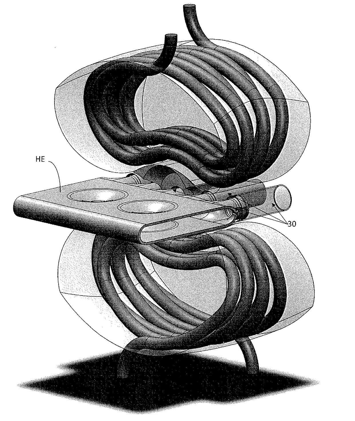
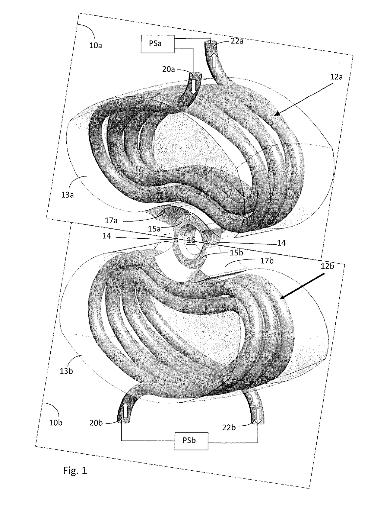
[0037]As seen in FIG. 1 is the weld head for magnetic pulse welding made as two independent weld head halves 10a and 10b, each half including at least one uninterrupted coil winding 12a and 12b respectively. The halves are brought together via abutting contacting surfaces 14, which encircles a work piece receiving zone 16. Each coil winding 12a and 12b is connected to an independent power source PSa and PSb, such that each coil winding could be controlled independently of the other coil winding.

[0038]Similar parts in upper and lower weld head half in figure are numbered with same numbers but with appendix “a” if located in upper half and with appendix “b” if located in lower half.

[0039]The design with two independent weld head halves enable the weld head to be moved into and out of contact with the welding position of the work piece located in the work piece receiving zone 16. Each weld head half includes at least one coil winding 12a / 12b, which have ends 20a,22a / 20b,22b connected t...


PUM

PropertyMeasurementUnit
central angleaaaaaaaaaa
areaaaaaaaaaaa
velocityaaaaaaaaaa

Abstract

The invention relates to a welding head for magnetic pulse welding of hollow thin-walled profile to an inner member having a complementary outer form to said hollow thin-walled profile. The weld head comprises two movable weld head halves (10a,10b) forming said weld head wherein each half has at least one individual induction coil (12a,12b) connected to a power source independently from the other weld head half, with coils wound in a kidney-shape. The work piece is clamped between shapers (15a,15b) integrated with each half. With this weld head could for example work pieces such as tubular thin-walled profiles be welded, even if they are integrated in a closed tubular design, as the weld head could be closed quickly over the welding position and opened for release of the work piece without experiencing arching in clamping area.

Description

FIELD OF THE INVENTION[0001]The present invention relates to a magnetic pulse welding device, and more particularly to a magnetic pulse welding head having a split coil design, thereby allowing opening and closing of the welding head around the welding point.BACKGROUND OF THE INVENTION[0002]The magnetic pulse welding (MPW) or forming process utilizes electromagnetic energy to create a metallurgical bound at molecular level without melting the materials to be joined. It was first developed in the 1970s and was disclosed in;[0003]Epechurin, V. P. ; “Properties of bimetal joints produced by magnetic-pulse welding”, Welding Productions, Vol. 21, No, 5 pp. 21-24 (1974), and[0004]Brown, W. F. & Bandas J & Olson N. T; “Pulsed magnetic welding of breeder reactor fuel pin and closures”, Welding Journal, No. 6, pp 22-26 (1978).[0005]The MPW process is based on well-established electromagnetic theory and is suitable for joining thin-walled tubular structures with either solid mandrels, or with...

Claims


Application Information

Patent Timeline
Patent Type & Authority Applications(United States)
IPC IPC(8): B23K20/06H05B6/36
CPCB23K20/06B23K2201/14H05B6/36H05B6/14B23K2101/14
Inventor APEL, MARTINPETTERSSON, KRISTER
Owner VALMET AB
Why Eureka
Try Eureka