
Method and apparatus for forming parts from a continuous stock material and associated forge

Inactive Publication Date: 2006-10-31
BLACK & DECKER INC
View PDF122 Cites 12 Cited by
  • Summary
  • Abstract
  • Description
  • Claims
  • Application Information

AI Technical Summary

Benefits of technology

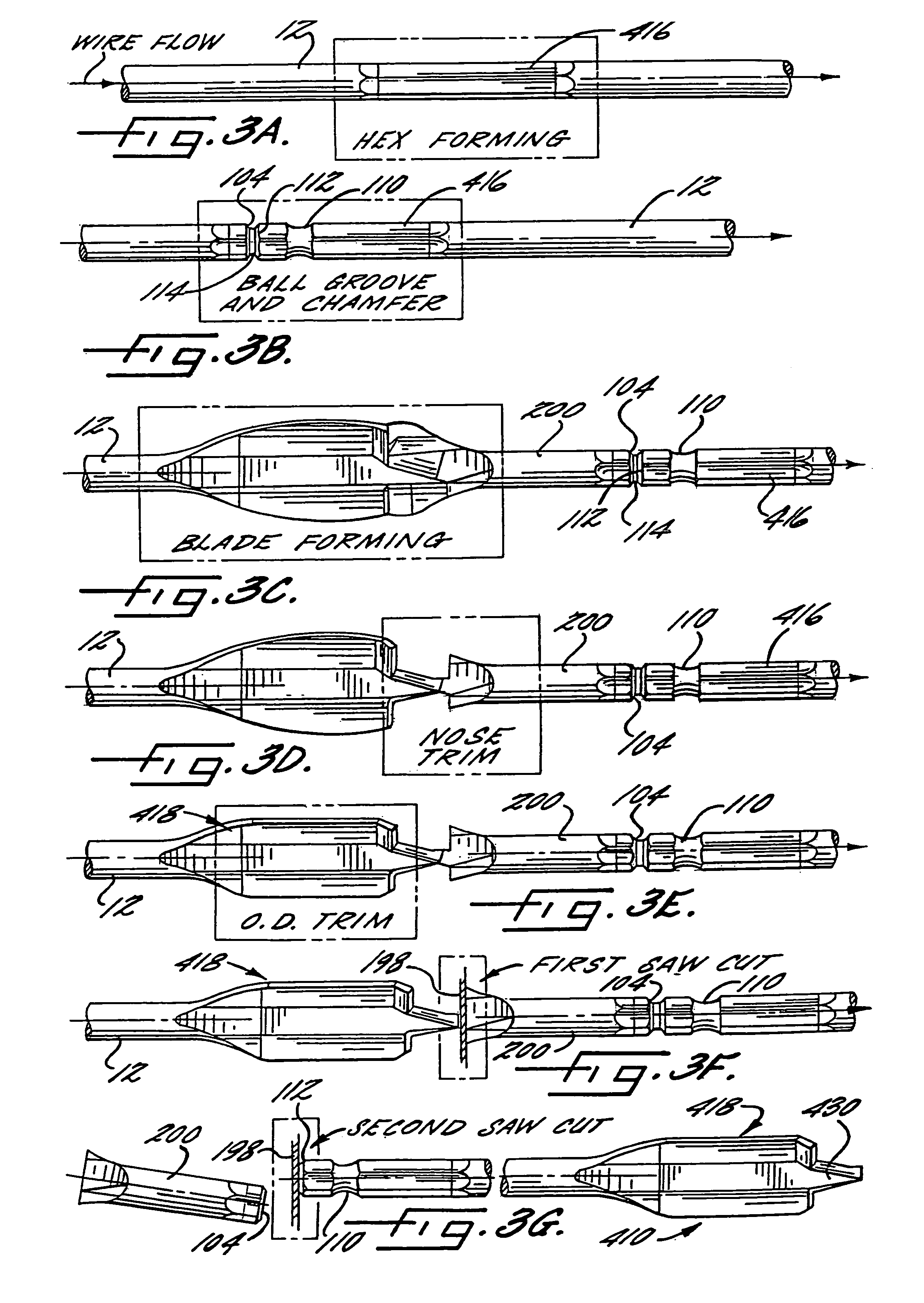
[0010]A method and apparatus is therefore provided according to the present invention for forming a plurality of parts, such as spade bits, from a continuous stock material. Thus, the various steps of the forming method of the present invention can be performed to predetermined portions of the continuous stock material, prior to separating the continuous stock material into a number of discrete parts. The efficiency of the forming process is thereby enhanced since individual parts need not be transported and oriented numerous times during the forming operations. By not requiring that the individual parts be handled during the forming operations, the quality and tolerance control of the parts formed by the forming method and apparatus of the present invention will also be enhanced since such handling of individual parts generally increases the opportunities for misalignment and contributes to poor tolerance control during the manufacturing process. In addition, the forming method and apparatus of the present invention effectively reduces the number of parts in process at any one time during the manufacturing process by limiting the number of batch operations required in comparison to conventional fabrication processes.

Problems solved by technology

Thus, even though parts are generally collected and transported between stages of these manufacturing processes in batches, these conventional manufacturing processes still generally require extensive handling of the parts in order to collect, transport and properly orient the parts between each stage of these manufacturing processes.
These conventional manufacturing processes also typically require a relatively large number of parts to be in process at all times due to the batch-type processing.
As will be apparent, the time and labor required to collect, transport and properly orient parts during these conventional manufacturing processes decreases the efficiency with which these parts are fabricated and, correspondingly, increases the cost of the resulting parts.
The inefficiencies created by handling and processing a plurality of discrete parts and the increased costs of maintaining a relatively large number of partially formed parts in process are particularly significant for those manufacturing processes which are designed to produce a large number of parts each day, such as tens of thousands, if not hundreds of thousands, of parts each day.
By initially cutting the wire stock and / or billets into a number of discrete pieces, however, the parts must be individually handled and processed throughout the hot forging process, thereby decreasing the efficiency with which the spade bits are fabricated and, correspondingly, increasing the resulting costs of the spade bits.

Method used


Image

  • Method and apparatus for forming parts from a continuous stock material and associated forge
  • Method and apparatus for forming parts from a continuous stock material and associated forge
  • Method and apparatus for forming parts from a continuous stock material and associated forge

Examples


Embodiment Construction

[0106]The present invention will now be described more fully hereinafter with reference to the accompanying drawings, in which a preferred embodiment of the invention is shown. This invention may, however, be embodied in many different forms and should not be construed as limited to the embodiments set forth herein; rather, this embodiment is provided so that this disclosure will be thorough and complete and will fully convey the scope of the invention to those skilled in the art. Like numbers refer to like elements throughout.

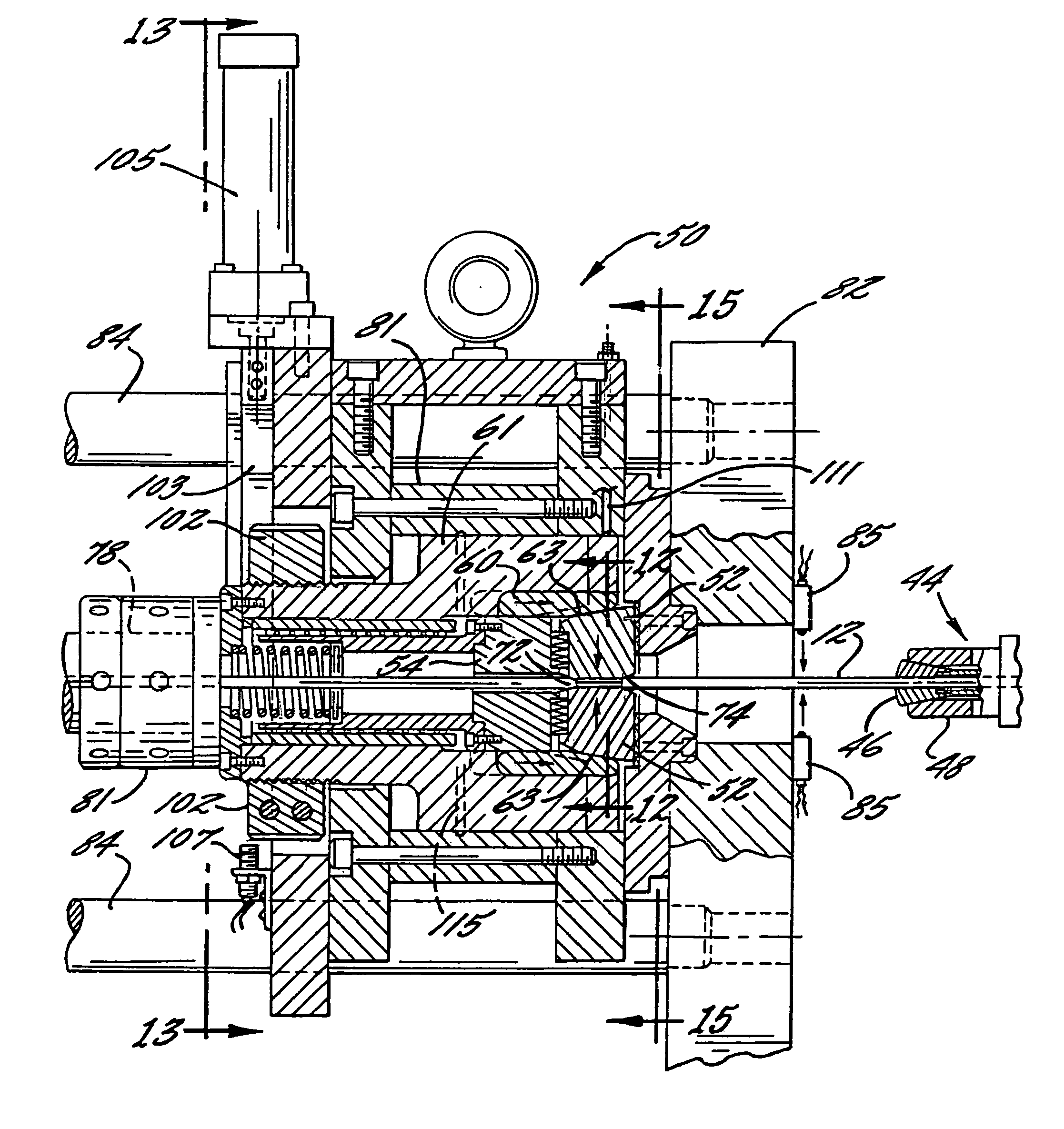
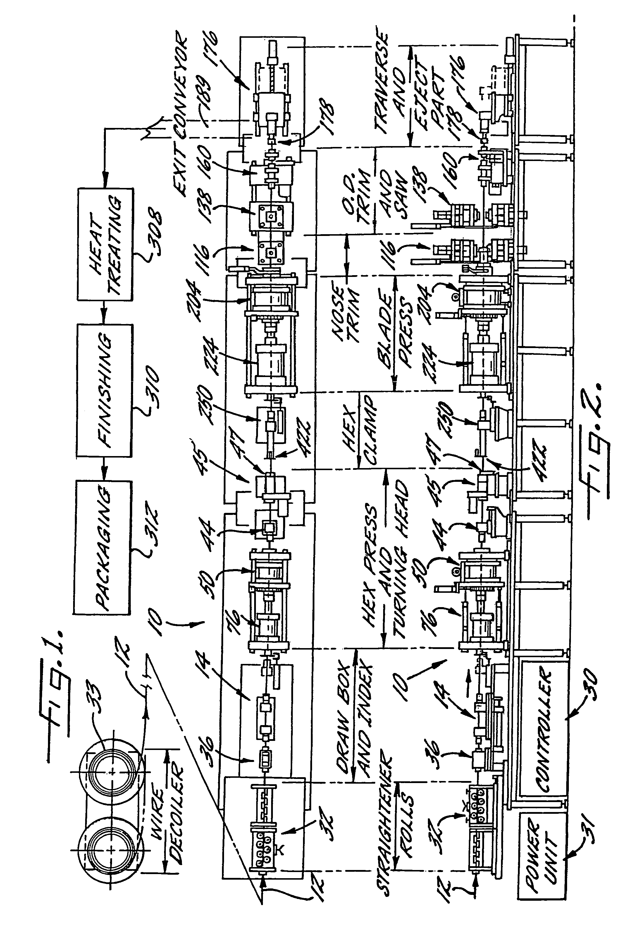
[0107]Referring now to FIGS. 1 and 2, a forming apparatus 10 according to one advantageous embodiment of the present invention is illustrated. As described in detail hereinbelow and as illustrated in FIGS. 1 and 2, the forming apparatus and associated method forms a plurality of parts from a continuous stock material 12. For purposes of illustration, however, the forming apparatus and method will be primarily described in conjunction with the formation of a pl...


PUM

PropertyMeasurementUnit
Fractionaaaaaaaaaa
Angleaaaaaaaaaa
Angleaaaaaaaaaa

Abstract

The present invention provides a method and apparatus for forming a plurality of parts, such as spade-type boring bits, from a continuous stock material. Thus, the various steps of the forming method of the present invention can be performed to predetermined portions of the continuous stock material prior to separating the continuous stock material into discrete parts, thereby enhancing the efficiency of the forming process. The present invention also provides an improved forge for forming portions of the continuous stock material into parts having a predetermined shape. The forge can be designed to provide a clearance region proximate the forward end of the ram to permit slight flexing of the forward end of the ram in a radially outward direction during forging operations. The forge can also include a lubrication system for lubricating its various components. In addition, the forge can incrementally rotate the ram after one or more parts have been forged. By repeating the incremental rotation of the ram, the forge will eventually rotate the ram a full 360°. An improved forging die is also provided which includes a back surface having a conical medial section and a pair of conical lateral sections that are recessed relative to the medial section such that forces will principally be applied to the medial section during forging operations.

Description

RELATED APPLICATIONS[0001]This application is a divisional of U.S. patent application Ser. No. 09 / 953,746 filed Sep. 17, 2001 now U.S. Pat. No. 6,739,171; which is a divisional of U.S. patent application Ser. No. 09 / 215,159 filed Dec. 18, 1998 and now issued Sep. 18, 2001 as U.S. Pat. No 6,290,439; which is a continuation-in-part of U.S. patent application Ser. No. 09 / 143,630 filed Aug. 28, 1998 now abandoned; which is a continuation of U.S. patent application Ser. No. 08 / 662,665 filed Jun. 14, 1996 and now issued Dec. 1, 1998 as U.S. Pat. No. 5,842,267; which is a continuation-in-part of U.S. patent application Ser. No. 08 / 366,986 filed Dec. 30, 1994 and now issued Dec. 23, 1997 as U.S. Pat. No. 5,700,113; and U.S. patent application Ser. No. 08 / 514,071 filed Aug. 11, 1995 and now issued Dec. 16, 1997 as U.S. Pat. No. 5,697,738, the contents of each being expressly incorporated in their entirety herein.FIELD OF THE INVENTION[0002]The present invention relates generally to methods a...

Claims


Application Information

Patent Timeline
IPC IPC(8): B21B45/00B21K5/02B21J5/12B21J9/00B21J9/02B21K27/02B23P15/28B27G15/00
CPCB21J5/12B21J9/00B21J9/02B21K5/02B21K27/02B27G15/00B23P15/28Y10T408/909Y10T408/9065Y10T29/5198Y10T408/906
Inventor BIEDERMAN, RONALD R.BUGANTO, LAWRENCE GEORGECROSBY, STEPHEN R.GURE, CHARLES P.MCKENZIE, TIMOTHY T.STONE, PAUL ANDREWTHOMAS, RICKEY JAMESWETHERINGTON, CHARLES T.
Owner BLACK & DECKER INC
Learn More