Method for mid load operation of auto-ignition combustion

a technology of auto-ignition combustion and mid-load range, which is applied in the direction of engine starters, electric control, instruments, etc., can solve the problems of retarded and slow hcci combustion, low mixture temperature, etc., and achieve the effect of decreasing the setting of the flow control valve, reducing the peak burning rate, and increasing the duration of the bum

Active Publication Date: 2006-10-31
MICHIGAN UNIV OF OFFICE OF TECH TRANSFER +1
View PDF20 Cites 46 Cited by
  • Summary
  • Abstract
  • Description
  • Claims
  • Application Information

AI Technical Summary

Benefits of technology

[0013]One-dimensional gas dynamic modeling analyses revealed that, for the case with the flow control valve closed, a large portion of the total recirculated burned gas in the cylinder is drawn from the cooler throttled intake port (about 440 deg K gas temperature) instead of re-breathing fully from the hotter exhaust port (about 740 deg K gas temperature). This results in a lower mixture temperature at intake valve closing (IVC), hence retarded and slower HCCI combustion. The effectiveness of using a port throttle for thermal management of the recirculated burned gas varies depending on port throttle setting. The effect is the strongest when the flow control valve is fully closed.

Problems solved by technology

This results in a lower mixture temperature at intake valve closing (IVC), hence retarded and slower HCCI combustion.

Method used


Image

  • Method for mid load operation of auto-ignition combustion
  • Method for mid load operation of auto-ignition combustion
  • Method for mid load operation of auto-ignition combustion

Examples


Embodiment Construction

[0031]For simplicity, the following description will address the present invention in its application to a single cylinder direct-injection gasoline four-stroke internal combustion engine, although it should be appreciated that the present invention is equally applicable to a multi-cylinder direct-injection or port-fuel-injected gasoline four-stroke internal combustion engine.

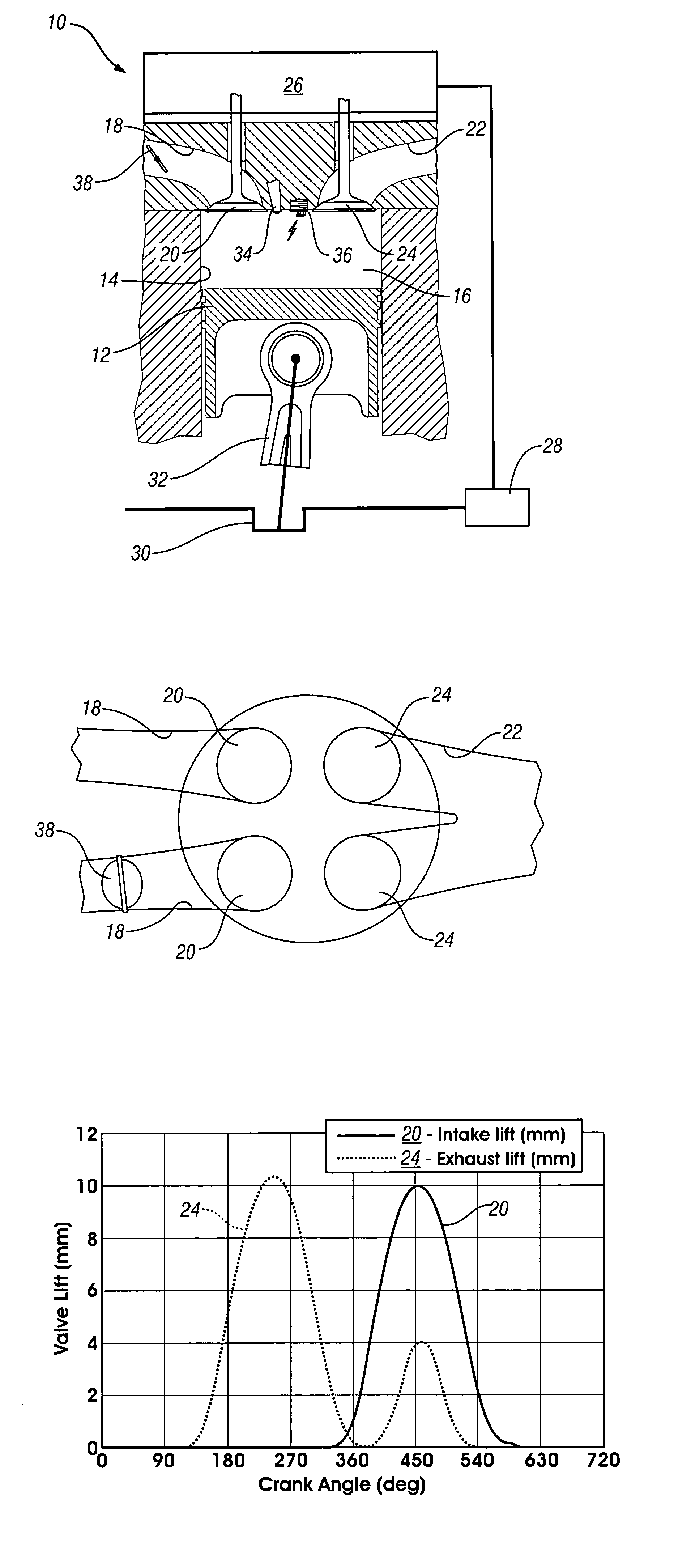
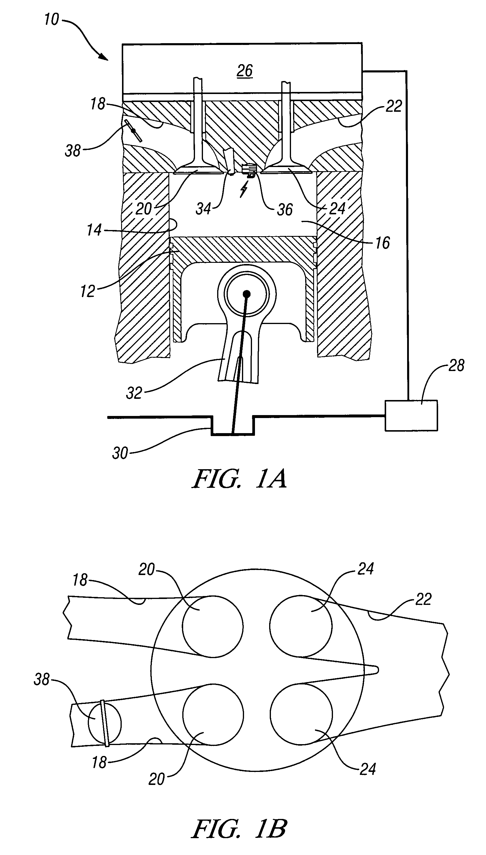
[0032]A schematic representation of an embodiment of the present invention is a single-cylinder direct-injection four-stroke internal combustion engine 10 shown in FIG. 1A. In the Figure, a piston 12 is movable in a cylinder 14 and defines with the cylinder 14 a variable volume combustion chamber 16. An intake passage 18 supplies air into the combustion chamber 16. Flow of air into the combustion chamber 16 is controlled by intake valve 20. Combusted gases can flow from the combustion chamber 16 via an exhaust passage 22 and flow of combusted gases through the exhaust passage 22 is controlled by exhaust valve 2...


PUM


Abstract

A method is disclosed for expanding the mid load range of a four-stroke gasoline direct-injection controlled auto-ignition combustion engine. The engine includes at least one cylinder containing a piston reciprocably connected with a crank and defining a variable volume combustion chamber including an intake valve controlling communication with an air intake and an exhaust valve controlling communication with an exhaust outlet. A system is employed for variably actuating the intake and exhaust valves. The valve actuating system is employable to operate the intake and exhaust valves with an exhaust re-compression or an exhaust re-breathing valve strategy. A reservoir chamber in communication with the combustion chamber is provided for temporary holding of residual burned gas. Residual burned gas in the combustion chamber and the exhaust outlet enters into the reservoir chamber and then loses thermal energy while in the reservoir chamber before being drawn back into the combustion chamber.

Description

CROSS-REFERENCE TO RELATED APPLICATIONS[0001]This application claims priority from U.S. Provisional Patent Application No. 60 / 587,120 filed Jul. 12, 2004.TECHNICAL FIELD[0002]The present invention relates to a method for extending the mid load range of a gasoline direct-injection controlled auto-ignition combustion engine, and more particularly to the use of a port throttle as an alternative to external exhaust gas recirculation (EGR) to dissipate some of the thermal energy associated with the internal residuals needed for controlled auto-ignition combustion and charge dilution.BACKGROUND OF THE INVENTION[0003]To improve the thermal efficiency of gasoline internal combustion engines, dilute combustion, using either air or EGR, is known to give enhanced thermal efficiency and lower NOx emissions. There is, however, a limit at which an engine can be operated with a diluted mixture because of misfire and combustion instability as a result of a slow burn. Known methods to extend the dil...

Claims


Application Information

Patent Timeline
Patent Type & Authority Patents(United States)
IPC IPC(8): F02M25/07F02B3/08F02B75/10G06F19/00F02N99/00
CPCF02D13/0207F02D13/0246F02D13/0273F02M25/0752F02B1/12F02B23/101F02B31/085F02B2023/108F02B2075/125F02D41/3035Y02T10/121Y02T10/123Y02T10/18F02M26/01Y02T10/12
Inventor KUO, TANG-WEINAJT, PAUL M.ENG, JAMES A.CHANG, JUNSEOKFILIPI, ZORAN S.ASSANIS, DIONISSIOS N.GURALP, ORGUN A.
Owner MICHIGAN UNIV OF OFFICE OF TECH TRANSFER
Why Eureka
Try Eureka