Peltier based freeze-thaw valves and method of use

a technology of freeze-thaw valves and peltiers, which is applied in the direction of lighting and heating apparatus, laboratory glassware, instruments, etc., can solve the problems of traditional valve technology configuration, reduced channel size and volume, and difficulty in managing the flow of liquids within small diameter channels, so as to avoid repetitive cyclic thermal stresses, reduce the effect of reducing the number of valves and reducing the size of the channels

Inactive Publication Date: 2006-10-31
WATERS TECH CORP
View PDF25 Cites 30 Cited by
  • Summary
  • Abstract
  • Description
  • Claims
  • Application Information

AI Technical Summary

Benefits of technology

[0007]The present invention provides a freeze-thaw valve using Peltier heat pump refrigeration where the Peltier device is constantly energized and where the valve state transition time (OPEN to CLOSED or CLOSED to OPEN) is minimized.
[0009]On the cold face of the Peltier stack, a cooled thermal mass is attached and is oriented with respect to a heated thermal mass with a small intervening gap through which is located a freeze-thaw segment of a fluidic conduit carrying the liquid to be frozen. The heated thermal mass is heated by a resistive heating element to maintain a temperature above the melting point of the liquid. Both the cooled thermal mass and the heated thermal mass are configured from material having a good thermal conductivity. The fluidic conduit is in intimate thermal contact with a movable low mass block having a high thermal conductivity. This low mass block, containing the fluidic conduit, can be moved alternately between contact with the heated mass and contact with the cooled mass. The relatively low thermal mass of the movable block coupled with high thermal conductivity allow its temperature to change rapidly when it is moved from a position contacting the heated or cooled thermal masses. This ability to rapidly change temperature by commutating the position of the movable block allows the freeze-thaw valve to be opened or closed within a short period of time without imposing large cyclic thermal stresses upon the Peltier stack.
[0010]In an alternative embodiment, the freeze-thaw valve according to the invention is housed within an enclosure, the interior of which is maintained under partial vacuum conditions. Evacuation of air and associated water vapor substantially eliminates frost buildup on the cold surfaces of the valve. High-quality vacuum can be further utilized to significantly reduce that component of heat transfer between the heated and cooled regions of the valve which is attributable to conduction and convection by air. The absence of air allows the enclosure, within this illustrative embodiment, to be constructed from materials having good thermal conductivity. The fabrication of the enclosure from a material having good thermal conductivity allows it to be used as a thermal circuit that thermally links the hot face of the Peltier heat pump with the heated thermal mass. The linkage of these two components allows the transfer of heat from the Peltier hot face to the heated thermal mass and dispenses with the need to heat the heated thermal mass with resistive heating elements.
[0012]The freeze-thaw valves according to the invention may be employed as simple isolation valves that protect other system components from extremes of pressure or they may be configured to create higher-order subsystems such as micro or nano-scale sample injectors or sample trapping subsystems.
[0013]Advantages of the valves according to the invention include the avoidance of repetitive cyclic thermal stresses to the Peltier device and resulting shortened lifespan by the ability to operate the Peltier heat pump at a substantially constant heat pumping rate. Additionally, the use of a constant cold-face temperature together with the commutating of the freeze-thaw segment to either the hot or cold thermal mass of the device avoids the slow response time associated with the thermal mass of the Peltier heat pump and allows for valve transition time to be minimized. The inventive freeze thaw valve also does not require a large consumable external cooling source such as in the prior art and therefore the use of the inventive freeze-thaw valve is permissible within smaller analytical devices. Further, the operation of the device within a vacuum enclosure avoids the frost buildup and subsequent failure of the freeze-thaw valve.

Problems solved by technology

The management of the flow of liquids within small diameter channels presents challenges as the scale of the channels and volumes of the liquids are reduced.
One significant constraint is the configuration of traditional valve technology.
The management of liquid flows in nano-liter volumes encounters significant limitation when the scale of fluid management is severely affected by poorly-swept or dead volume that is inherent within traditional switching methods.
Unfortunately, the aspiration of the jet of cold gas at the freeze-thaw segment can lead to a build up of frost that acts as insulation, reducing the efficiency of refrigeration and allowing the temperature within the freeze-thaw segment to rise.
This elevated temperature, within the freeze-thaw segment, results in the eventual failure of the valve.
Additionally, a large volume of gas is needed to operate these prior art freeze-thaw valves.
Unfortunately, such cascades typically do not respond rapidly enough when a drive voltage is applied, because in order to change temperature they must transfer heat associated with their own thermal mass.
Additionally, when rapid and / or large-magnitude changes are made in device temperature, thermal stresses induced by such changes contribute to degradation of the device and shortening of device lifespan.
Unfortunately, the operation of a Peltier heat pump in a constant pumping mode is not conducive to its use in freeze-thaw valving, because in order to properly utilize freeze-thaw valving it is necessary to be able to both freeze and thaw the same selected segment of a fluidic conduit.

Method used


Image

  • Peltier based freeze-thaw valves and method of use
  • Peltier based freeze-thaw valves and method of use
  • Peltier based freeze-thaw valves and method of use

Examples


Embodiment Construction

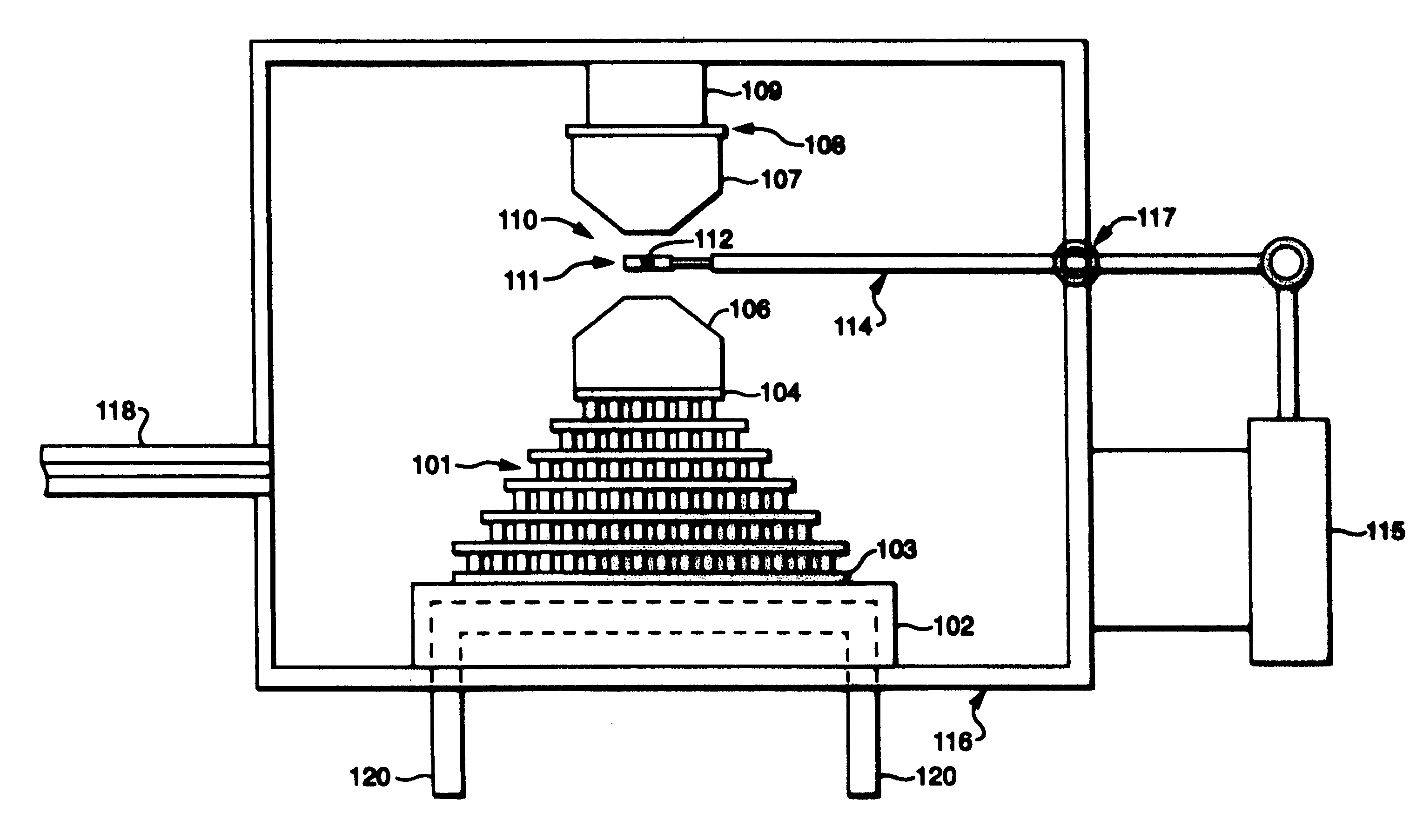
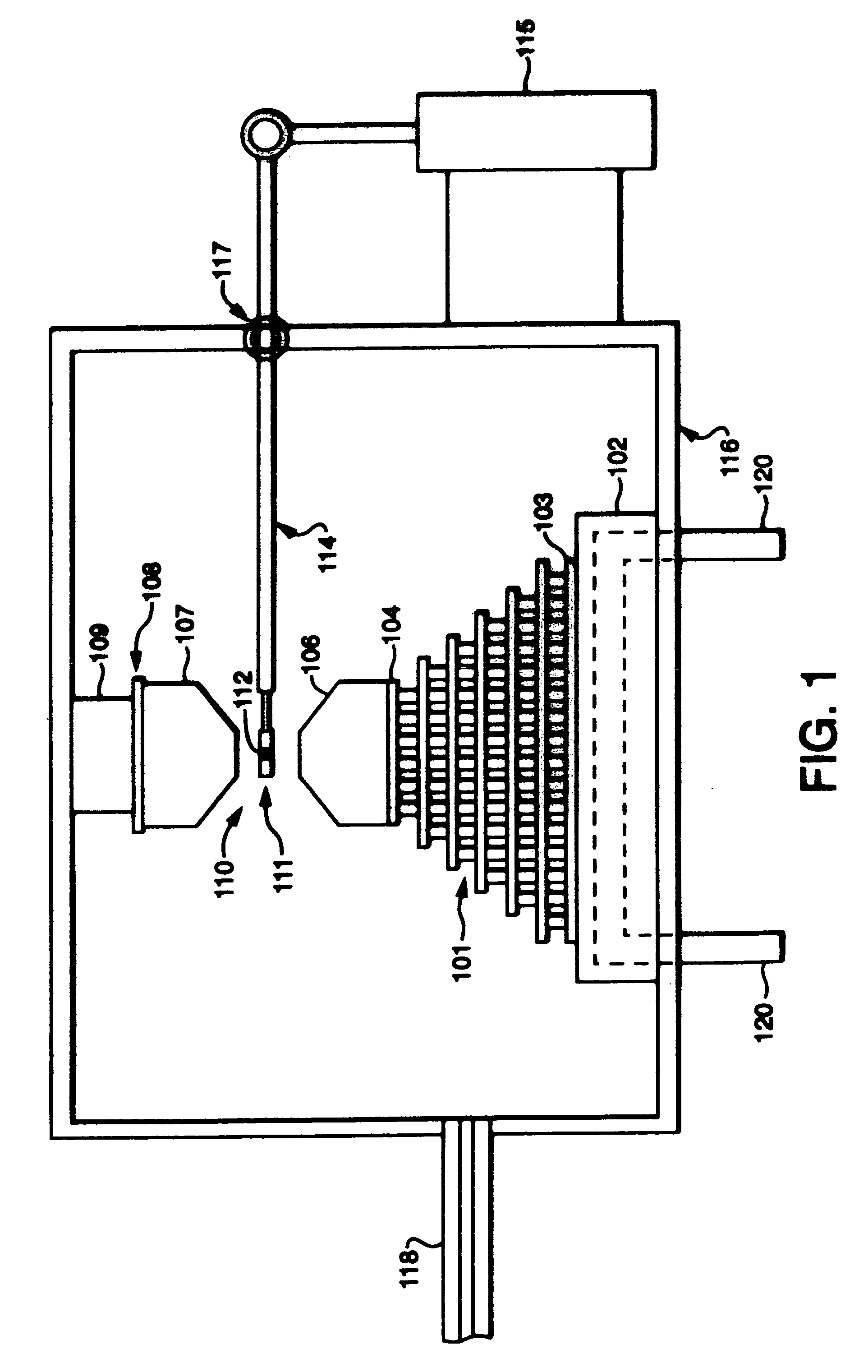
[0019]Turning to FIG. 1, an illustrative freeze-thaw valve according to the invention is shown. This illustrative freeze-thaw valve is cooled by a Peltier stack 101 having a hot face 103 and a cold face 104. The hot face 103 of the Peltier stack 101 is mounted to a heat exchange surface 102. The heat exchange surface 102 is comprised of a cross-drilled copper water jacket or manifold. This heat exchange surface 102 allows heat to be removed from the hot face 103 of the Peltier stack 101 that results from both the useful heat pumping and power dissipation within the electrical drive elements within the Peltier stack 101. The water jacket contained within the heat exchange surface 102 is typically one component of a liquid circulation path having a small radiator and circulation pump. The circulation path connects to the water jacket at coolant ports 120. The cold face 104 of the Peltier stack 101 is affixed to a cooled thermal mass 106. The cooled thermal mass 106 is configured from ...


PUM

PropertyMeasurementUnit
temperatureaaaaaaaaaa
temperaturesaaaaaaaaaa

Abstract

A freeze-thaw valve is provided using a Peltier heat pump where the thermal short-circuit path between a cooled thermal mass and a heated thermal mass is reduced or absent and the valve state transition time is minimized. The freeze-thaw valve comprises a Peltier heat pump mounted to a heat exchange surface that comprises a cross-drilled copper water jacket or manifold. The Peltier heat pump is operated to maintain a cooled thermal mass at a substantially constant low temperature. A resistance heating element is used to produce a heated thermal mass. The freeze-thaw segment of a fluid conduit is commutated to contact either the heated or the cooled thermal mass to thaw and therefore open the valve or cool and thus close the valve. The operation of the Peltier heat pump at a constant temperature avoids problems inherent in the use of a Peltier heat pump to both heat and cool a freeze thaw segment.

Description

CROSS REFERENCE TO RELATED APPLICATIONS[0001]This application claims benefit of and is a continuation of International Application No. PCT / US03 / 039071, filed Dec. 9, 2003 and designating the United States, which claims benefit of and priority to U.S. Provisional Application No. 60 / 431,810, filed Dec. 9, 2002. The entire contents of these applications are incorporated herein by reference.FIELD OF THE INVENTION[0002]This invention relates generally to freeze-thaw valve technologies that are capable of performing a high-pressure isolation function.BACKGROUND OF THE INVENTION[0003]The management of the flow of liquids within small diameter channels presents challenges as the scale of the channels and volumes of the liquids are reduced. One significant constraint is the configuration of traditional valve technology. The management of liquid flows in nano-liter volumes encounters significant limitation when the scale of fluid management is severely affected by poorly-swept or dead volume ...

Claims


Application Information

Patent Timeline
Patent Type & Authority Patents(United States)
IPC IPC(8): F17D1/18F15C1/04B01L3/00F15C1/08F16K13/10F16K99/00F25B21/02G01N30/20G05D23/19H01L35/32
CPCB01L3/502738F16K13/10F16K99/0001F16K99/0003F16K99/0021F16K99/0044F25B21/02G01N30/20G05D23/1919H01L35/325B01L2300/1822B01L2300/1827B01L2400/0677F16K2099/0084G01N35/1097G01N2030/303G01N2030/204Y10T137/6606Y10T137/0391Y10T137/2251Y10T137/2196H10N19/101F16K29/00F17D1/18
Inventor DOURDEVILLE, THEODORE A.
Owner WATERS TECH CORP
Why Eureka
Try Eureka