Inkjet printer

a technology of inkjet printers and printers, applied in the direction of printing, etc., can solve the problems of degrading printing accuracy and complicated support mechanisms, and achieve the effect of improving printing accuracy correspondingly

Active Publication Date: 2006-10-31
BROTHER KOGYO KK
View PDF14 Cites 22 Cited by
  • Summary
  • Abstract
  • Description
  • Claims
  • Application Information

AI Technical Summary

Benefits of technology

[0009]The invention was developed to solve the forgoing problems. The invention provides an inkjet printer in which it is unnecessary to move an inkjet head to cover the nozzle surface thereof with a sealing member, so that the printing accuracy can be improved, while the moving path of the sealing member is set under the inkjet head so that ink can be prevented from adhering to the inkjet head.
[0011]With this configuration, when the conveyance belt is located at the conveyable position and the sealing member is located at the first position, the conveyance belt presses the sealing member toward the nozzle surface so that the sealing member covers the nozzle surface. Accordingly, the nozzle surface can be covered with the sealing member with the ink-jet head being fixed. In the operation of covering the nozzle surface with the sealing member, it is therefore unnecessary to move the inkjet head as in the background-art inkjet printer, but the inkjet head can be designed to be fixed. Thus, there is an effect that the positional accuracy of the inkjet head is secured so that the printing accuracy can be improved correspondingly.
[0012]In addition, after the operation of covering the nozzle surface with the sealing member is terminated, the first moving unit may move the sealing member along the outer circumference of the conveyance belt to the second position located under the conveyance belt. Thus, there is an effect that ink ejected in a purging process or the like and reserved in the sealing member can be prevented from flowing down onto the inkjet head. As a result, it is possible to avoid such an accident that the inkjet head is contaminated with the ink flowing down or an electric system is short-circuited due to the ink flowing down so that the inkjet head can be prevented from being damaged or failing.

Problems solved by technology

However, in the aforementioned inkjet printer, the head chips have to be moved toward the maintenance members at the time of capping.
Accordingly, the head chips have to be supported movably so that a support mechanism therefor becomes complicated.
Thus, there is a problem that the positional accuracy of the head chips is apt to get out of order so as to degrade the printing accuracy.
Thus, there is a problem that not only are the head chips contaminated with the ink, but an electric system is also short-circuited due to the flowing-down ink so as to cause damage or failure of the head chips.

Method used


Image

  • Inkjet printer
  • Inkjet printer
  • Inkjet printer

Examples


Embodiment Construction

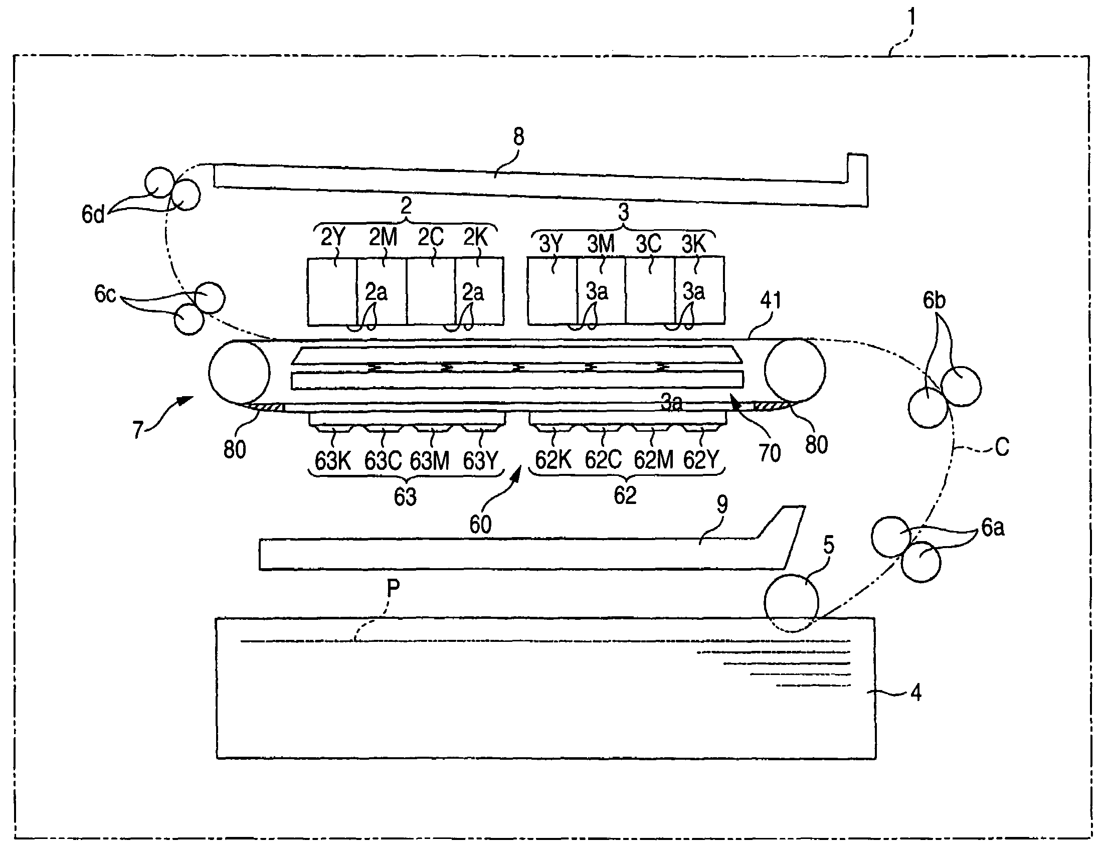
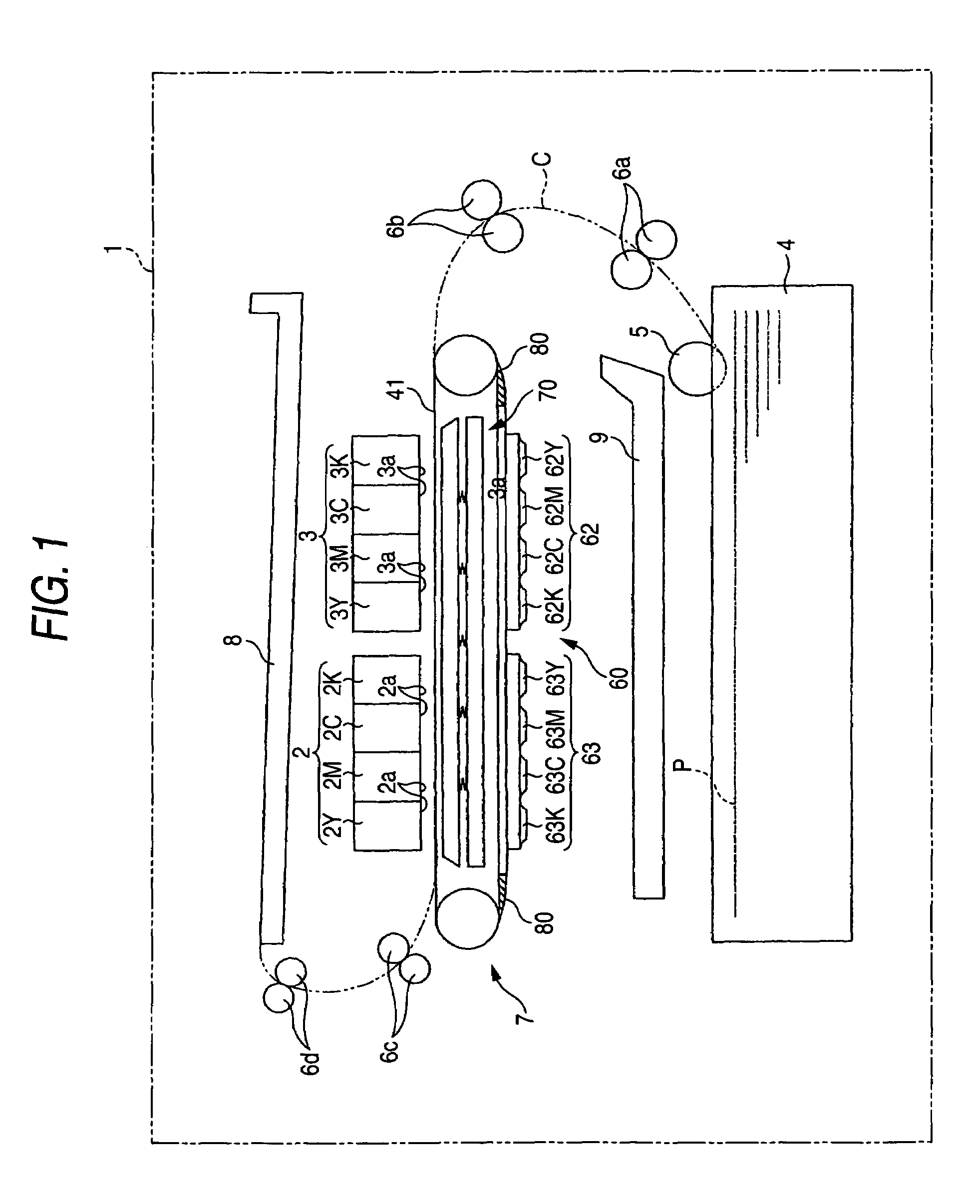
[0026]A preferred embodiment of the invention will be described below with reference to the accompanying drawings. FIG. 1 is a schematic view schematically showing the overall configuration of an inkjet printer 1 according to the embodiment of the invention. In FIG. 1, a conveyance path C of recording paper (recording medium) P is shown by use of the chain double-dashed line.

[0027]The inkjet printer 1 is designed as a line type printer that has first and second head units 2 and 3, and can print a full-line image without scanning the recording medium in the width direction thereof with the first and second head units 2 and 3. As shown in FIG. 1, the inkjet printer 1 chiefly includes a paper feed cassette 4, a paper feed roller 5, guide rollers 6a–6d, a conveyance belt unit 7 serving as a constituent component of a conveyance unit for conveying the recording medium, a paper discharge tray 8 and an ink reception member 9.

[0028]Inks of four colors (cyan, magenta, yellow and black) are s...


PUM


Abstract

An inkjet printer includes an inkjet head, a sealing member, a conveyance unit, a first moving unit, and a second moving unit. The first moving unit moves the sealing member along an outer circumference of the conveyance belt between a first position and a second position. The first position is located above the conveyance belt and faces the nozzle surface of the inkjet head. The second position is located under the conveyance belt. The second moving unit moves the conveyance belt between a conveyable position and a separate position. When the conveyance belt is located at the conveyable position and the sealing member is located at the first position, the conveyance belt presses the sealing member toward the nozzle surface so that the sealing member covers the nozzle surface.

Description

BACKGROUND OF THE INVENTION[0001]1. Field of the Invention[0002]The present invention relates to an inkjet printer, and particularly relates to an inkjet printer in which it is unnecessary to move an inkjet head to cover the nozzle surface thereof with a sealing member, so that the printing accuracy can be improved, while the moving path of the sealing member is set under the inkjet head so that ink can be prevented from adhering to the inkjet head.[0003]2. Description of the Related Art[0004]In an inkjet printer, nozzles for ejecting ink are exposed to the air. Accordingly, there is a fear that ink in the nozzles is evaporated to clog the nozzles when ink ejection is not performed. Therefore, the nozzle surface of the inkjet head is generally capped (covered) with a cap member (sealing member) to prevent the ink from being evaporated when the ink ejection operation is suspended for a long time.[0005]The cap member is disposed out of a printing area. The capping of the nozzle surfac...

Claims


Application Information

Patent Timeline
Patent Type & Authority Patents(United States)
IPC IPC(8): B41J2/165
CPCB41J2/16585
Inventor OKAMOTO, TSUGIOKUZUYA, SUSUMUNAKASHIMA, ATSUHISA
Owner BROTHER KOGYO KK
Why Eureka
Try Eureka