Ink supply system, recording apparatus, recording head, and liquid supply system
a technology of liquid supply system and recording head, which is applied in the direction of printing, etc., can solve the problems of inability to recover the functions of the recording head in some cases, inability to perform normal discharge operation of ink, and inability to achieve the recovery of functions of the recording head, etc., to achieve rapid and smooth discharge, quick and smooth discharge, and secure the effect of ink preservation stability
- Summary
- Abstract
- Description
- Claims
- Application Information
AI Technical Summary
Benefits of technology
Problems solved by technology
Method used
Image
Examples
first embodiment
[0067](First Embodiment)
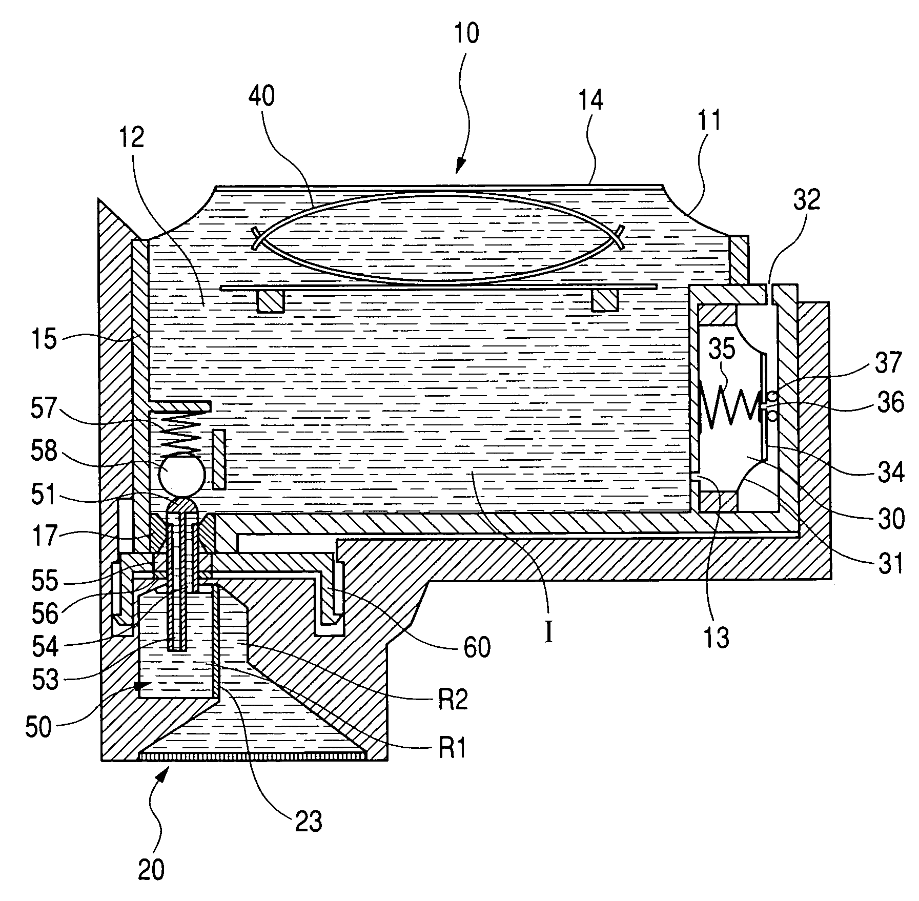
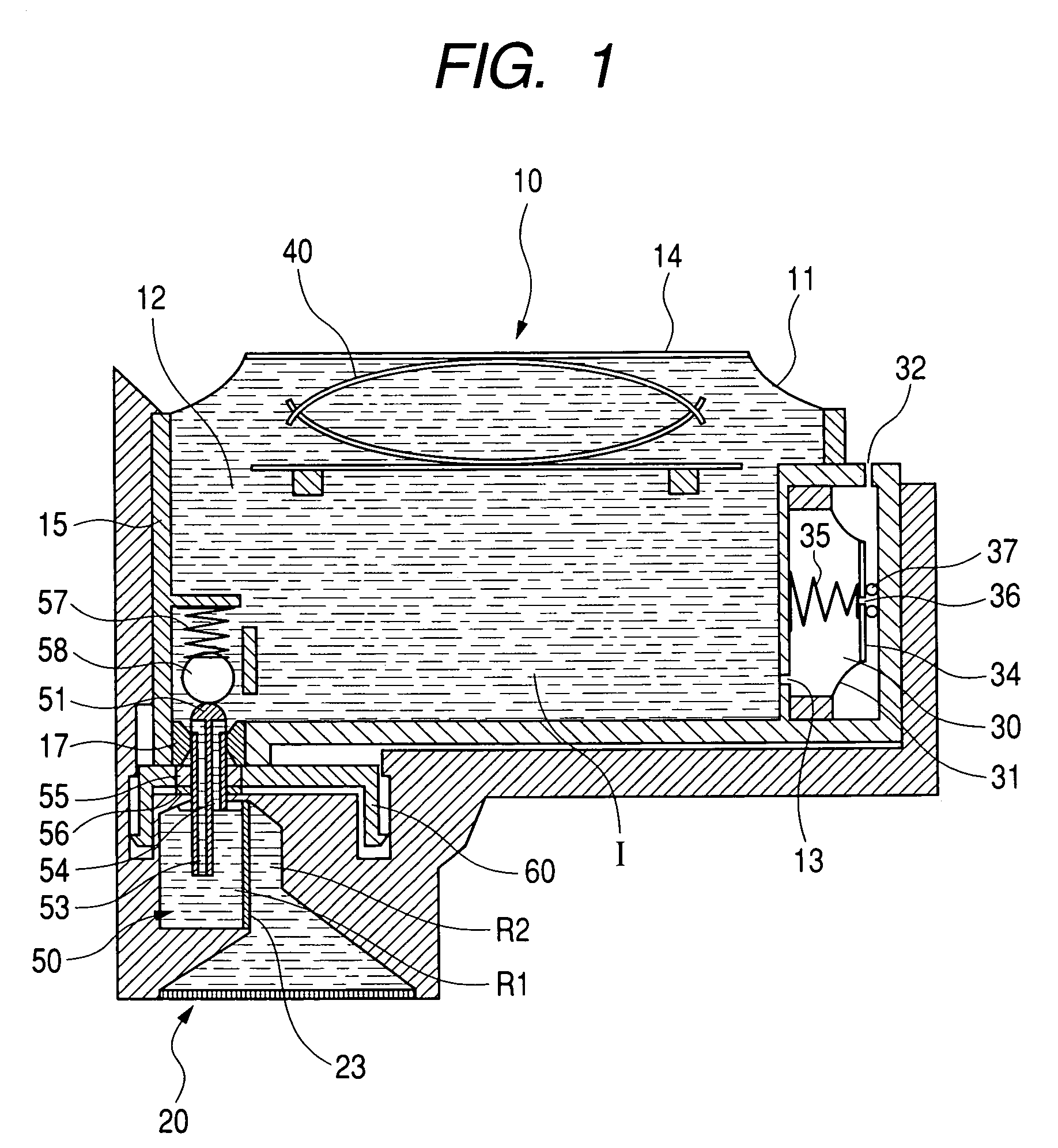
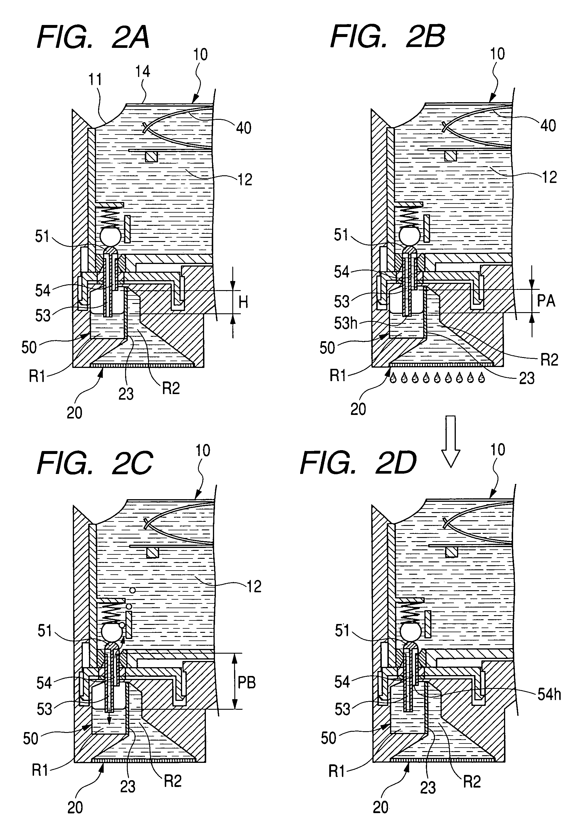
[0068]FIG. 1 is an exemplary cross section of a liquid supply system according to the first embodiment of the present invention. Generally, an ink supply system in FIG. 1 comprises: an ink tank 10 as a liquid storage container; an ink jet recording head 20 (hereinafter, called only “recording head”); and a liquid chamber 50 forming an ink supply path for connection therebetween. Although, in the present embodiment, the liquid chamber 50 and the recording head 20 are integrated into one body so that the chamber 50 and the head 20 can not be separated, the chamber 50 may be configured to be done so that the chamber 50 and the recording head 20 can be separated. Moreover, there may be a configuration in which the liquid chamber 50 is provided in a carriage equipped with the recording head 20, the ink tank 10 can be detached from the upper portion of the carriage, and an ink supply path from the ink tank 10 to the recording head 20 is formed when the ink tank 10 ...
second embodiment
[0110](Second Embodiment)
[0111]FIG. 4 is an exemplary sectional view of an ink supply system which explains a second embodiment according to the present invention.
[0112]The difference between the above-described first embodiment and the present one is that the head side opening position in the air flow path 54 is equal to that of the upper inner wall surface in the liquid chamber 50, all the air remaining in the first region R1 is exhausted when the air in the first region R1 is exhausted into the ink tank 10, and there is no air remaining in the first region R1. In this case, when the quantity of the air remaining in the second region R2 exceeds a predetermined quantity, the air is moved into the first region R1, and the quantity of the air in the second region R2 is kept within the predetermined quantity. However, as the first region R1 is filled only with ink even when air movement is generated, a meniscus is quickly formed in the filter 23 and the air movement is stopped. Accord...
third embodiment
[0113](Third Embodiment)
[0114]FIG. 5 is an exemplary sectional view of an ink supply system which explains a third embodiment according to the present invention.
[0115]In the present example, the upper portion of a filter 23 is subjected to water repelling processing, for example, by which a water repelling material is painted on the portion, and the painted portion is called a portion 23A. The contact angle with ink at the portion 23A in which the water repelling processing is performed is increased, and a meniscus pressure Pm (Refer to FIG. 3A) at the portion 23A is reduced. Therefore, the quantity of the air remaining in a second region R2 is reduced, and the air movement is started even when the difference HA between the gas-liquid interface of a first region R1 and that of the second region R2 is small. Accordingly, air can be exhausted even when the filter 23 is arranged at an angle with respect to the horizontal direction as shown in FIG. 5. As a result, the space efficiency i...
PUM
 Abstract
Description
Claims
Application Information
 - R&D
- Intellectual Property
- Life Sciences
- Materials
- Tech Scout
- Unparalleled Data Quality
- Higher Quality Content
- 60% Fewer Hallucinations
Browse by: Latest US Patents, China's latest patents, Technical Efficacy Thesaurus, Application Domain, Technology Topic, Popular Technical Reports.
© 2025 PatSnap. All rights reserved.Legal|Privacy policy|Modern Slavery Act Transparency Statement|Sitemap|About US| Contact US: help@patsnap.com


