
Motion-coupled visual environment for prevention or reduction of motion sickness and simulator/virtual environment sickness

a visual environment and motion-coupled technology, applied in the field of prevention or reduction of motion sickness, can solve the problems of inconvenience and discomfort, more serious problems, countless trips and vacations have been spoiled, etc., to prevent, reduce and treat motion sickness, and alleviate the discord of spatial information. , the effect of preventing, reducing or at least delaying the onset of motion sickness

Active Publication Date: 2006-10-31
MICROSOFT TECH LICENSING LLC +1
View PDF16 Cites 48 Cited by
  • Summary
  • Abstract
  • Description
  • Claims
  • Application Information

AI Technical Summary

Benefits of technology

[0026]The present invention solves these problems by providing a new kind of motion coupled visual environment that can be used to prevent, reduce and treat motion sickness. One preferred exemplary illustrative embodiment couples physically indicated motion of the inertial environment to motion of a visually presented scene. This coupling alleviates the discord of spatial information from the principal spatial senses such as visual, vestibular and other proprioceptive receptors.
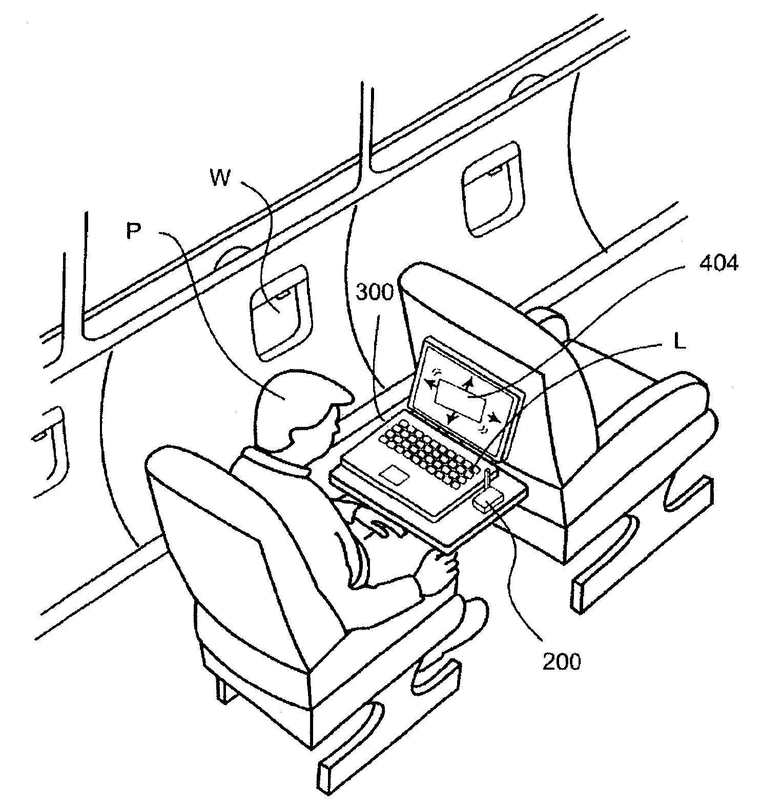
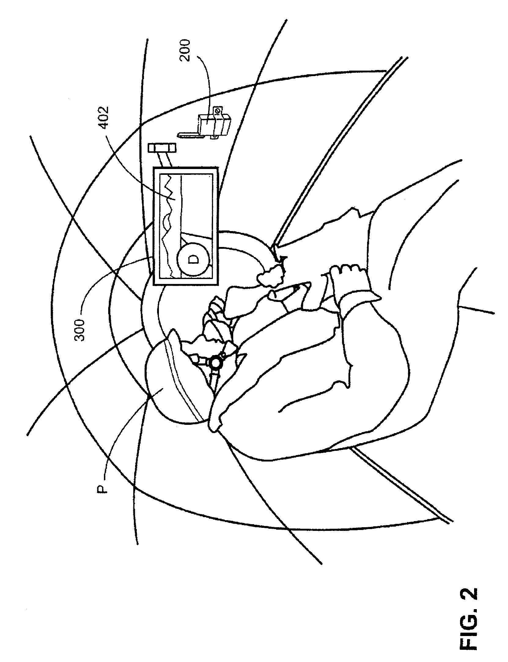
[0027]One possible illustrative arrangement, for example, is to display the cockpit view of an aircraft moving over terrain on a computer display. This display is presented on a motion platform that is independent of the display such as a ship at sea, an automobile in motion or many other platforms. Inertial and other types of sensors record motion information, and aspects of this information are fed back into the computer display. For example, a sensed heave (vertical motion) may be shown as a slight pitch or a roll of ten degrees may be shown as a roll of two degrees. Various algorithms may be used to map motion into display information are possible. The user then simply views the display, which will prevent, reduce or at least delay onset of motion sickness for healthy individuals and will even relieve motion sickness for users that are already symptomatic.
[0028]A motion coupled visual environment reduces the incidence and severity of motion sickness as compared with exposure to an inertial environment alone. This reduction in motion sickness may be significant. One example illustrative implementation of a motion-coupled visual environment generator includes four components:

Problems solved by technology

Countless trips and vacations have been spoiled by motion sickness.
Moreover, motion sickness generally does not go away immediately upon removal of the stimulus making the person sick, but rather takes some time to subside These symptoms often cause inconvenience and discomfort, and may in some instances cause more serious issues.
Some people get motion-sickness every time they ride in a car, on a plane or in a ship.
For example, one may get motion sickness while stationary if exposed to large format immersive displays such as commonly employed by simulators, virtual environments (VE), high-definition television, military displays and other display systems.
Most medications for motion sickness have undesirable side effects such as drowsiness, and the efficacy of alternative health products has not been proven in clinical trials.
This may not help a passenger who unexpectedly gets motion-sickness.
This decoupling can arise from a mismatch between visually presented scene motion and physically experienced motion.
Such a stabilized but uncoupled image may actually abet the onset of motion sickness rather than abating it.
Exposure to an uncoupled visual environment and inertial environment may in some cases produce significantly more severe sickness than exposure to just the virtual environment or just the motion platform.
However, we have found no human subject research in the open, scientific literature that supports this approach for alleviating motion sickness.
Once again, it is unclear how such a display would function or whether it would succeed in reducing motion sickness.
Since motion of the individual is be sensed, the device appears to be limited to simulators and virtual environments in stationary environments.
One drawback of this approach is that a grid of lines may be insufficient to cause the visual system to orient to the grid as opposed to the environment in the room.
In both cases, however, it seems unlikely that users will perceive the line patterns as representing a visual environment with which to orient themselves.
Another potential drawback of this prior approach is that these cues could interfere with whatever tasks one is performing.
Thus, while much work has been done in the past, no one has yet developed a truly effective display-based technology for reducing, eliminating or alleviating motion sickness.
While cues may tell the user what is occurring in the inertial environment, they generally do not alleviate the discord perceived by the spatial senses.
For example, the presence of an attitude indicator in the cockpit of an aircraft does not prevent a pilot from becoming motion sick.
Simply knowing one's position relative to the Earth's frame of reference is generally insufficient information to recouple discordant visual and proprioceptive environments.
Motion sickness induction on these platforms is generally greatest when visual access to the inertial environment is limited either physically or perceptually.
Motion sickness can also occur even if the user has good visibility of the external environment and is not distracted from viewing it.
This may happen in an aircraft, for example; the aircraft may heave in the vertical direction by many feet at a rate that is highly evocative, and yet if the aircraft is at a great enough altitude, the visually presented scene can only barely be perceived to move.
This can create a dissonant visual and inertial environment and thus motion sickness.

Method used


Image

  • Motion-coupled visual environment for prevention or reduction of motion sickness and simulator/virtual environment sickness
  • Motion-coupled visual environment for prevention or reduction of motion sickness and simulator/virtual environment sickness
  • Motion-coupled visual environment for prevention or reduction of motion sickness and simulator/virtual environment sickness

Examples


Embodiment Construction

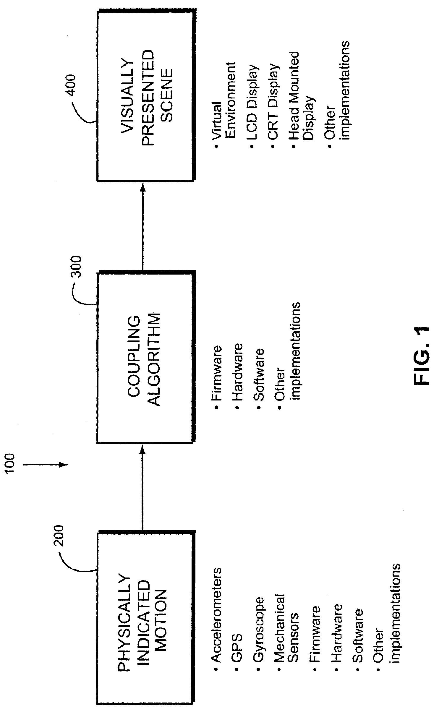
[0059]FIG. 1 shows an example non-limiting illustrative embodiment of a system 100 providing a motion-coupled visual environment. In the FIG. 1 example shown, system 100 includes three main components: a sensing arrangement 200 that detects the physically indicated motion, a coupling arrangement and associated algorithm 300 that couples the physically indicated motion and a presenting arrangement 400 that presents an evocative scene.

[0060]In the example embodiment, the sensing arrangement 200 includes one or more sensors that sense inertial motion. In one example embodiment, sensing arrangement 200 is disposed somewhere on the same platform carrying the person (e.g., mounted to a vehicle frame, vehicle floor, transport platform etc.). Sensing arrangement 200 can sense motion using any of a variety of different sensor types or combinations thereof, including for example:[0061]accelerometer(s)[0062]Global Positioning System (GPS)[0063]Gyroscope(s)[0064]Mechanical sensor(s)[0065]Inclin...


PUM


Abstract

A motion-coupled visual environment prevents, reduces and / or treats motion sickness by sensing inertial motion and providing a corresponding evocative image for a subject to view. Inertial sensors may include accelerometers, gyroscopes or a variety of other different sensor types. A cross-coupling algorithm may be used to cross couple different sensed inertial motions. A variety of mapping schemes may be used to map sensed inertial motion to corresponding motion within the evocative scene displayed on the display. Applications include reducing motion sickness on passenger vehicles such as airplanes, trains and cars; on military vehicles such as ships, airplanes, helicopters and the like; and reducing “cybersickness” in the context of simulations on moving platforms.

Description

CROSS-REFERENCES TO RELATED APPLICATIONS[0001]Not applicable.STATEMENT REGARDING FEDERALLY SPONSORED RESEARCH OR DEVELOPMENT[0002]Not applicable.FIELD OF THE INVENTION[0003]The present invention relates to the prevention or reduction of motion sickness by creating a motion concordant visual environment.BACKGROUND AND SUMMARY OF THE INVENTION[0004]Countless trips and vacations have been spoiled by motion sickness. Motion sickness symptoms range from the distracting, such as eyestrain and blurred vision, to the debilitating, such as nausea, depression and apathy. Moreover, motion sickness generally does not go away immediately upon removal of the stimulus making the person sick, but rather takes some time to subside These symptoms often cause inconvenience and discomfort, and may in some instances cause more serious issues. Imagine for example a motion-sick soldier who must function effectively in combat immediately after being transported by airplane, ship or helicopter.[0005]Motion ...

Claims


Application Information

Patent Timeline
Patent Type & Authority Patents(United States)
IPC IPC(8): A61M21/00
CPCA61M21/00A61M21/02A61M2021/0022A61M2021/005A61M2205/507G16H20/70G16H40/63
Inventor BRENDLEY, KEITH W.MARTI, JED
Owner MICROSOFT TECH LICENSING LLC
Learn More