Thermal memory cell and memory device including the thermal memory cell

a memory cell and thermal memory technology, applied in the field of thermal memory cells/devices, can solve the problems of phase-change media above the glass temperature very low, affecting the performance of the device, and affecting the write/erase process, so as to achieve the effect of easy control of the write/erase process

Inactive Publication Date: 2006-10-31
GLOBALFOUNDRIES US INC
View PDF13 Cites 17 Cited by
  • Summary
  • Abstract
  • Description
  • Claims
  • Application Information

AI Technical Summary

Benefits of technology

[0031]In another aspect, the memory cells in the inventive memory device may include a storage medium having a programmable electrical impedance, a heater in thermal communication with the storage medium for programming the electrical impedance, and a counter-electrode in electrical communication with the storage medium, for facilitating a reading of the electrical impedance by the heater. In this case, the control device may facilitate writing information to and erasing information from the storage medium, and to read information from the storage medium.
[0037]With its unique and novel features, the present invention provides a memory cell which makes controlling of the write / erase process much easier than in conventional devices. Specifically, the present invention provides a memory cell in which the primary current path for reading / writing / erasing does not necessarily involve the storage medium (e.g., the phase-change media) directly.

Problems solved by technology

Although, due to the large difference in electrical resistivity between the amorphous and crystalline state (about a factor of 100) the read dynamic range is substantial, this approach is accompanied with several problems, which are discussed in more detail below.
Clearly, such large electrical resistances can cause major problems if they are part of the write / erase circuit.
Although Poole-Frenkel conduction through the phase-change media lowers the device impedance at bias fields of larger than 3×10⁵ V / cm, the high temperatures in combination with large electric fields may easily irreversibly degrade (e.g., by breakdown, which is strongly temperature dependent) the phase-change material, and therefore compromise the device performance.
In addition, as a further complication, the resistance of the phase-change media above the glass temperature is very low, which makes the controlling of the write / erase process very difficult.

Method used


Image

  • Thermal memory cell and memory device including the thermal memory cell
  • Thermal memory cell and memory device including the thermal memory cell
  • Thermal memory cell and memory device including the thermal memory cell

Examples


Embodiment Construction

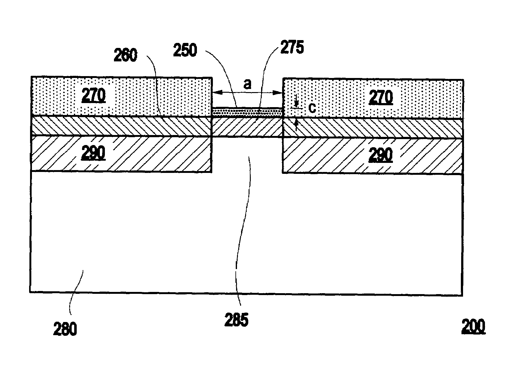
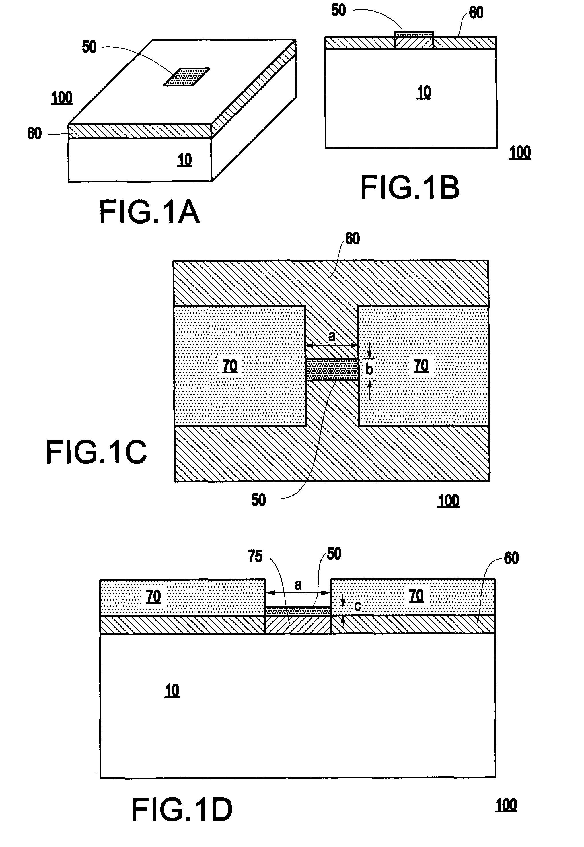
[0047]Referring now to the drawings, and more particularly to FIGS. 1A–1B, the present invention includes a thermal memory cell 100 for storing information. The memory cell 100 includes a storage medium 60 having a programmable thermal impedance, and a heater 50 (e.g., a resistive heater) in thermal communication with the storage medium 60 for programming the thermal impedance.

[0048]Specifically, the heater 50 (e.g., a “virtual” heater in the form of a surface heat load) may be used to process information (e.g., writing / erasing / reading) in the memory cell 100. In addition, the storage medium 60 may include a phase-change medium such as an amorphous / crystalline phase-change medium. The memory cell 100 may also include a substrate 10 on which the storage medium 60 is formed, and which may function as a heat sink.

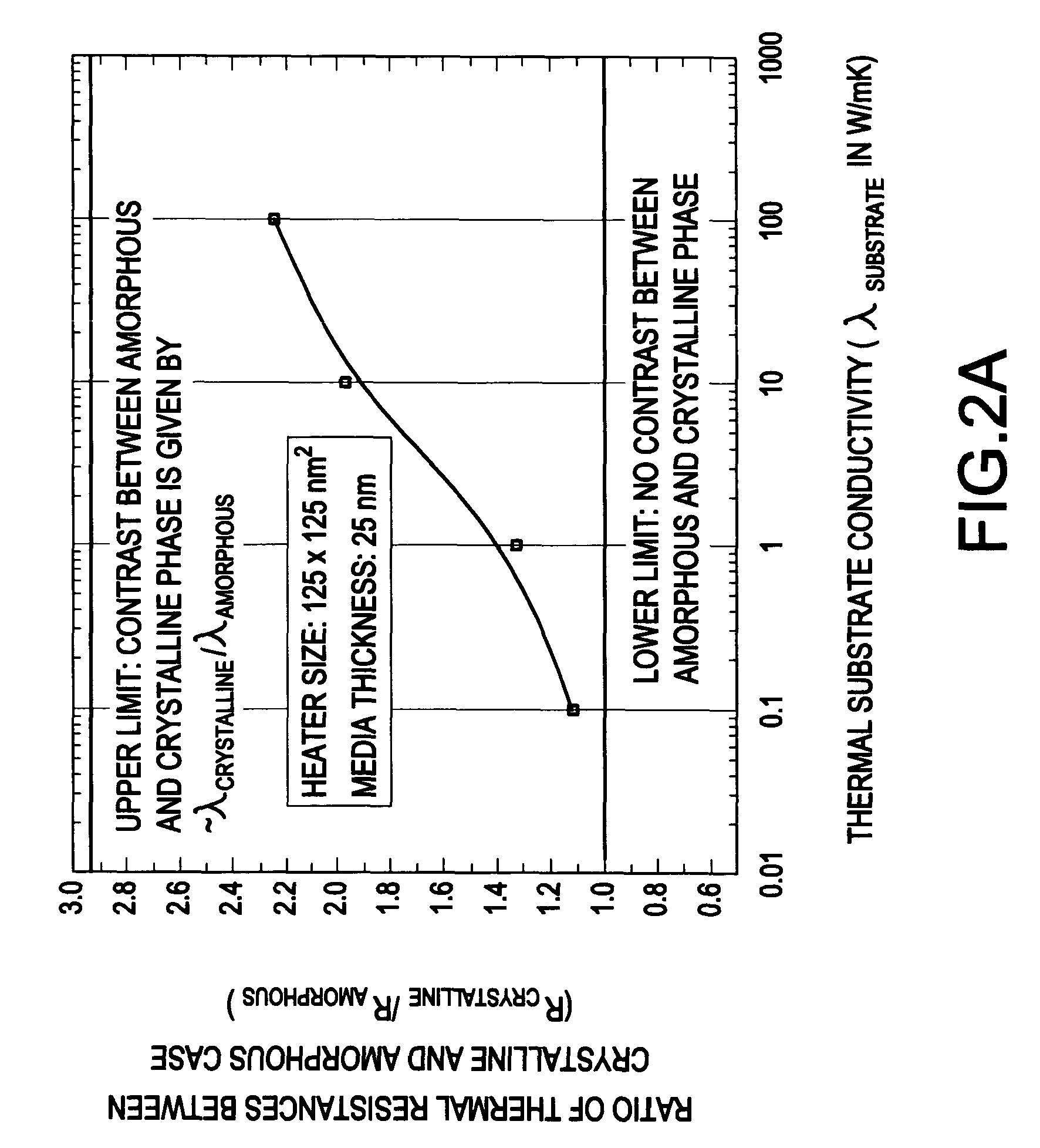
[0049]The present invention recognizes some of the above-referenced problems of the conventional phase-change memory devices and addresses them by realizing writing and erasin...


PUM


Abstract

A memory cell includes a storage medium having a programmable thermal impedance, and a heater in thermal communication with the storage medium for programming the thermal impedance. In another aspect, a memory cell includes a storage medium having a programmable electrical impedance, and a heater in thermal communication with the storage medium for programming the electrical impedance. In a third aspect, a memory device includes a plurality of the memory cells in accordance with the first and / or second aspect of the present invention.

Description

CROSS REFERENCE TO RELATED APPLICATIONS[0001]This Application is related to U.S. patent application Ser. No. 09 / 773,346 filed on Jan. 31, 2001, entitled “An assembly suitable for reading / writing / erasing information based on thermal coupling”, having U.S. patent application Ser. No. 09 / 774,851 filed on Jan. 31, 2001, entitled “An assembly suitable for reading data based on thermal coupling”, having U.S. patent application Ser. No. 09 / 774,943 filed on Jan. 31, 2001, entitled “An assembly for writing and / or erasing high density data on a media”, having U.S. patent application Ser. No. 09 / 773,323 filed on Jan. 31, 2001, entitled “A method for writing and / or erasing high density data on a media”, all of which are assigned to International Business Machines Corporation and are incorporated herein by reference.BACKGROUND OF THE INVENTION[0002]1. Field of the Invention[0003]The present invention generally relates to a thermal memory cell / device for reading / writing and erasing information an...

Claims


Application Information

Patent Timeline
Patent Type & Authority Patents(United States)
IPC IPC(8): H01L29/00G11C16/02H01L27/24H01L37/00H01L45/00
CPCG11C7/04G11C13/0004G11C13/0069H01L45/06H01L45/122H01L45/1286H01L45/144H01L45/148G11C2013/008H01L27/2436H10B63/30H10N70/231H10N70/821H10N70/8613H10N70/884H10N70/8828
Inventor HAMANN, HENDRIK F.O'BOYLE, MARTIN PATRICKWICKRAMASINGHE, H. KUMAR
Owner GLOBALFOUNDRIES US INC
Why Eureka
Try Eureka