Harmonic rejection mixer and method of operation

a mixer and harmonic technology, applied in the field of radio frequency receivers, can solve the problems of insufficient total available suppression from existing methods, inability to achieve adequate out-of-band harmonic suppression, and inability to manufacture high-performance radios, etc., to achieve superb suppression and suppress unwanted responses.

Inactive Publication Date: 2006-10-31
NAT SEMICON CORP
View PDF17 Cites 122 Cited by
  • Summary
  • Abstract
  • Description
  • Claims
  • Application Information

AI Technical Summary

Benefits of technology

[0007]The present invention provides a harmonic rejection mixer that overcomes the problems inherent in the prior art. A harmonic rejection mixer (HRM) inserts nulls at harmonic frequencies to suppress unwanted responses. This technique is based on the frequency notching property of classical finite-impulse response (FIR) filters. The delay elements that...

Problems solved by technology

However, a major drawback of switching mixers is that the mixer output responds to odd harmonic frequencies of the local oscillator (LO) signal.
In designing modern radio transceivers with stringent out-of-band specifications, the total available suppression from existing methods is always found to be i...

Method used


Image

  • Harmonic rejection mixer and method of operation
  • Harmonic rejection mixer and method of operation
  • Harmonic rejection mixer and method of operation

Examples


Embodiment Construction

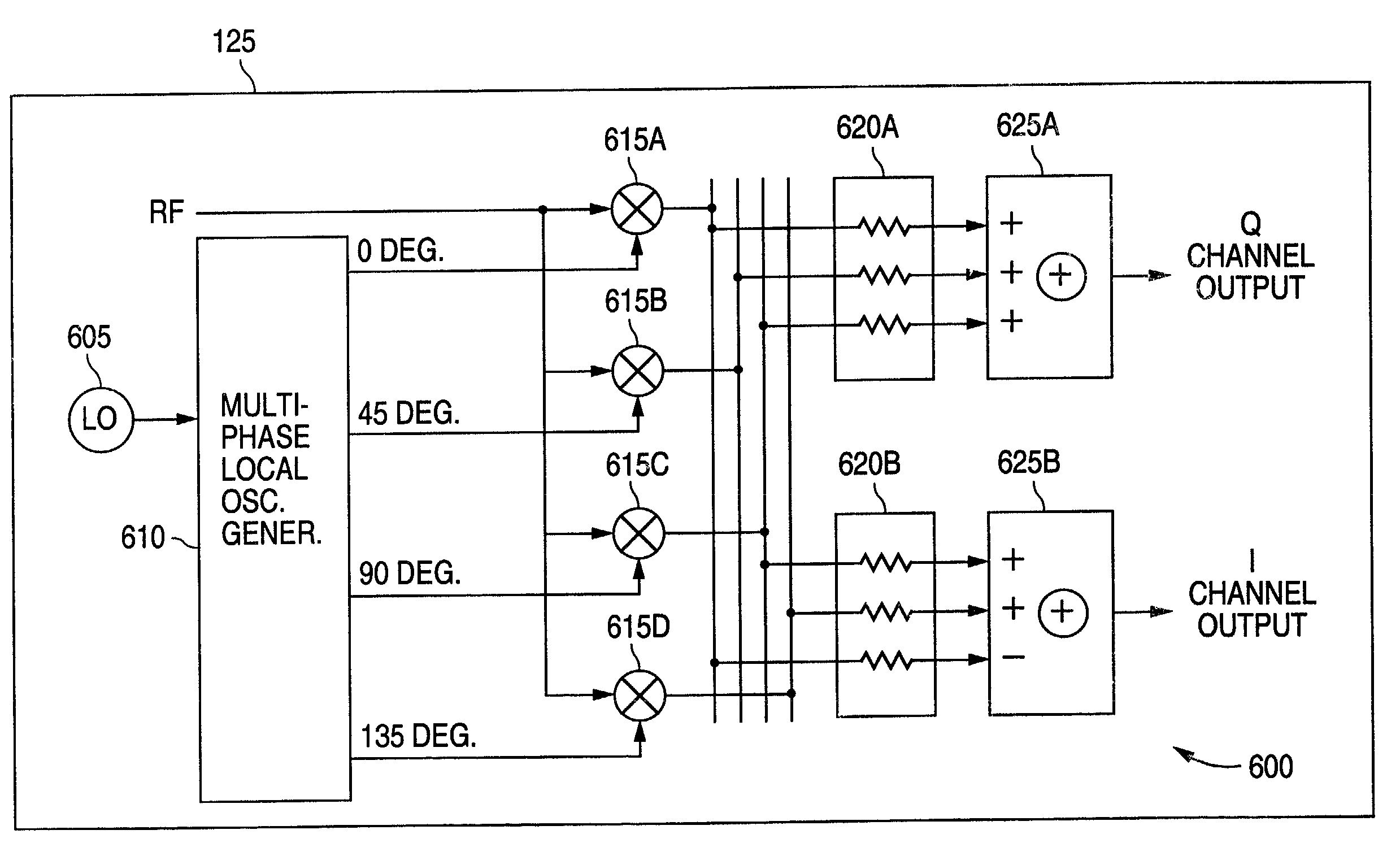
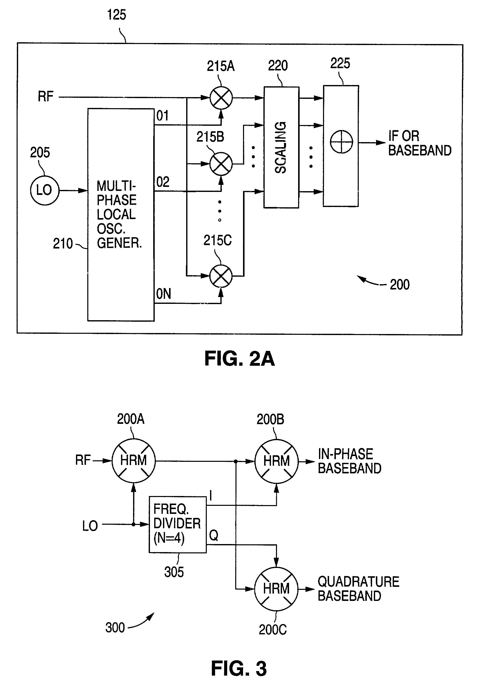
[0024]FIGS. 1 through 11, discussed below, and the various embodiments used to describe the principles of the present invention in this patent document are by way of illustration only and should not be construed in any way to limit the scope of the invention. Those skilled in the art will understand that the principles of the present invention may be implemented in any suitably arranged radio frequency (RF) receiver.

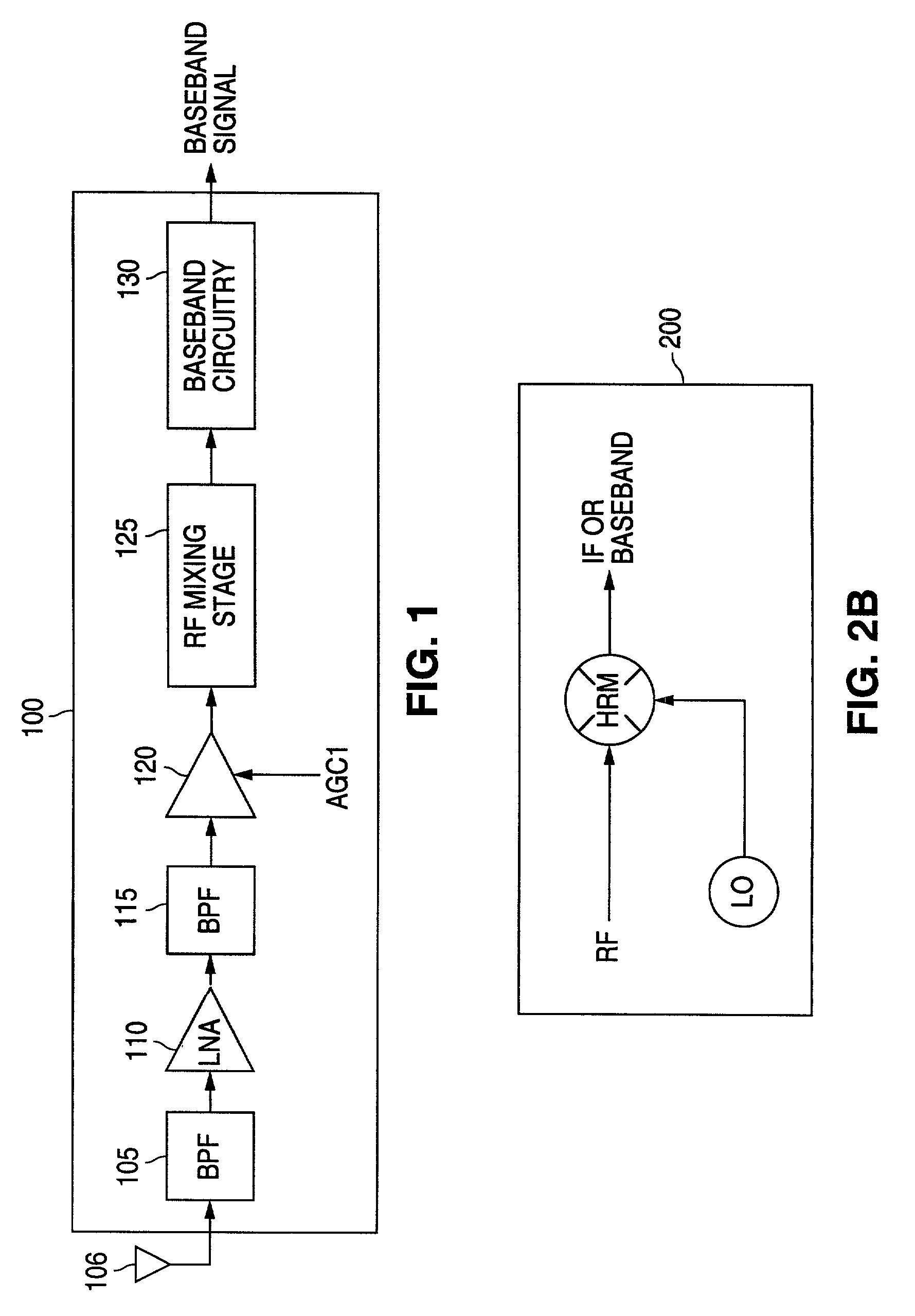
[0025]FIG. 1 illustrates selected portions of the receive signal path of exemplary RF receiver 100 according to one embodiment of the present invention. RF receiver 100 may be implemented in any conventional one-way or two-way RF communication device, including a cell phone, a wireless network card, a two-way pager, and the like. For the purpose of simplifying the explanation of the present invention, the transmitter portion of a two-way communication embodiment of the present invention is not shown.

[0026]The RF receive path through RF receiver 100 comprises band pass fi...


PUM


Abstract

A radio frequency (RF) demodulation circuit comprising a harmonic rejection mixing stage capable of receiving and mixing an incoming radio frequency (RF) signal having a frequency RF and a reference local oscillator (LO) signal having a frequency LO and generating an output signal in which out-of-band harmonic signals are suppressed. The harmonic rejection mixing stage comprises 1) a multiphase local oscillator (LO) generator for receiving the reference LO signal and generating M phase-shifted local oscillator signals having frequencies LO and 2) M mixers, each of the M mixers receiving the incoming radio frequency signal and one of the M phase-shifted local oscillator signals. Each of the M mixers generates a subcomponent signal. The subcomponent signals are then scaled and combined to produce the output signal.

Description

TECHNICAL FIELD OF THE INVENTION[0001]The present invention is generally directed to radio frequency (RF) receivers and, in particular, to a harmonic rejection mixer.BACKGROUND OF THE INVENTION[0002]Business and consumers use a wide array of wireless devices, including cell phones, wireless local area network (LAN) cards, global positioning system (GPS) devices, electronic organizers equipped with wireless modems, and the like. The increased demand for wireless communication devices has created a corresponding demand for technical improvements to such devices. Generally speaking, more and more of the components of conventional radio receivers and transmitters are being fabricated in a single integrated circuit (IC) package. In particular, single chip radios with no off-chip channel filters are very popular. Direct conversion receivers and software-defined radios are being developed in order to simplify single chip designs and to make each design suitable for as many applications as ...

Claims


Application Information

Patent Timeline
IPC IPC(8): H04B1/00H04B1/26
CPCH03D7/12H04B1/30H03D2200/0086
Inventor WONG, HEEJU, SHU-INGSCHWARTZ, MICHAELBUTLER, ROBERT K.
Owner NAT SEMICON CORP
Why Eureka
Try Eureka