Elastic surface wave device

Active Publication Date: 2009-08-20
TAIYO YUDEN KK
View PDF8 Cites 15 Cited by
  • Summary
  • Abstract
  • Description
  • Claims
  • Application Information

AI Technical Summary

Benefits of technology

[0026]As described above, it is possible to efficiently suppress unw

Problems solved by technology

The achievable performance of a surface acoustic wave device is limited by a piezoelectric substrate used, and therefore a material having large piezoelectricity and satisfactory temperature stability is required.
On the other hand, since the surface acoustic wave device is used as a filter, unwanted responses which occur from various causes obstruct characteristics thereof.
However, i

Method used


Image

  • Elastic surface wave device
  • Elastic surface wave device
  • Elastic surface wave device

Examples


embodiment 1

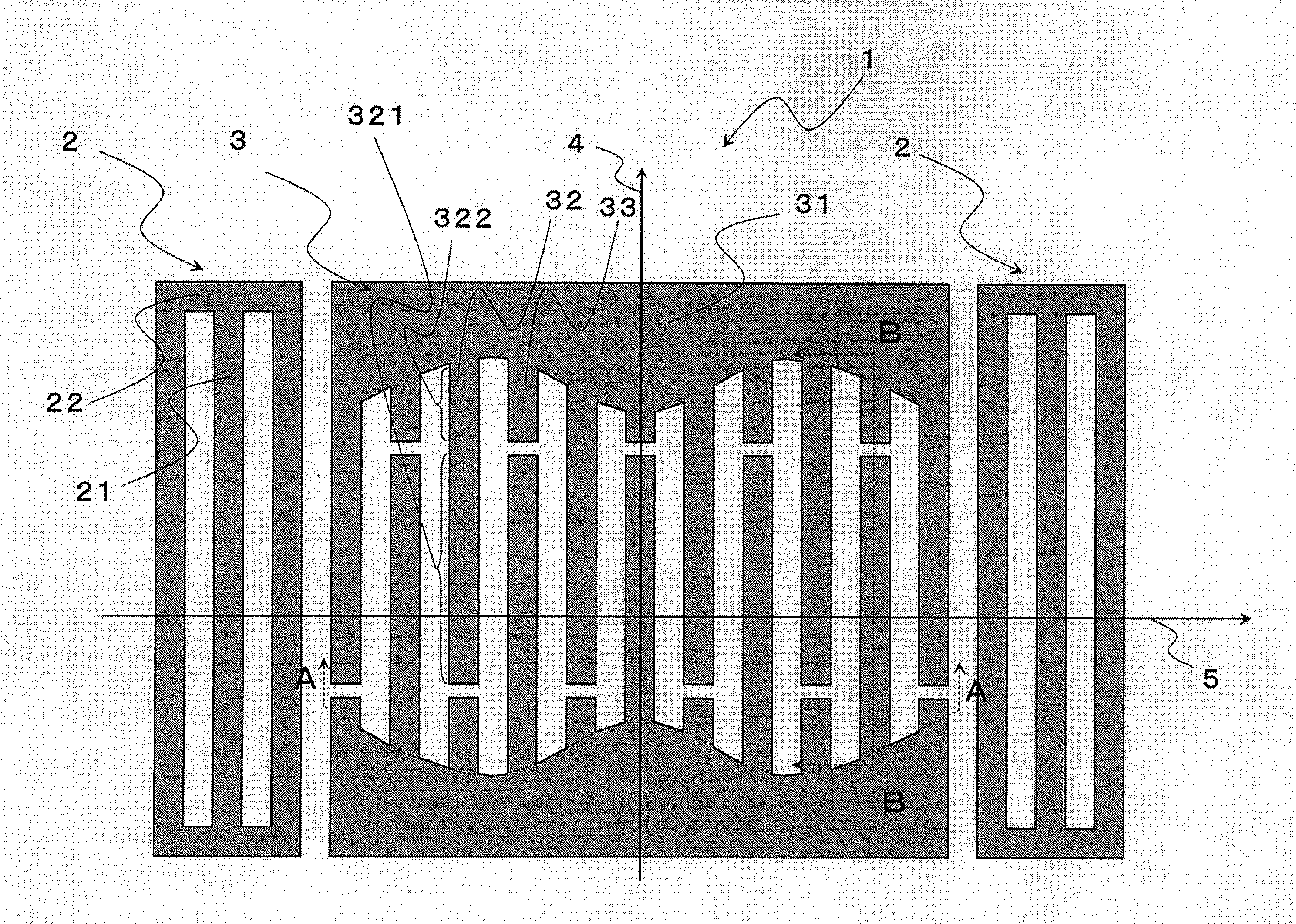
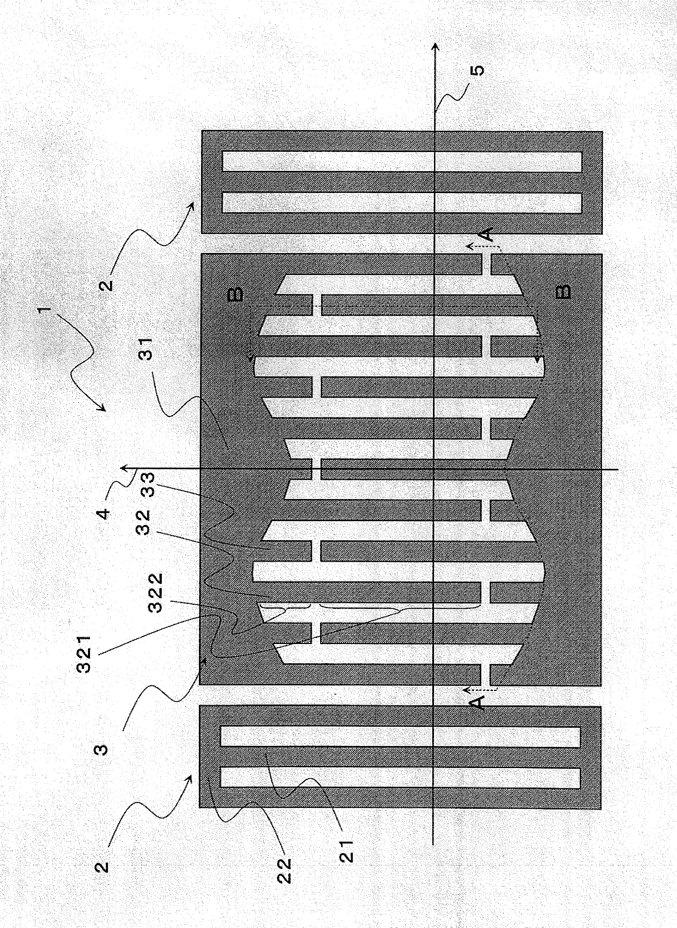
[0046]FIG. 1 shows a schematic view of a surface acoustic wave device according to this embodiment. An elastic resonant wave device 1 according to this embodiment is constructed of a pair of reflectors 2 formed opposed to each other on a substrate and an interdigital transducer (hereinafter simply referred to as “IDT”) 3 arranged between this pair of reflectors 2, and the IDT 3 has a pair of common electrodes 31 and a plurality of cross electrodes 32 each having a interdigitated portion 321 and a dummy portion 322 and a plurality of dummy electrodes 33 are connected to each of the common electrodes 31. The plurality of cross electrodes connected to one of the common electrodes and a plurality of cross electrodes of the opposed common electrode cross each other and are arranged in a comb-like form.

[0047]The surface acoustic wave device according to this embodiment applies a voltage between the pair of common electrodes 33 of the IDT 3, causes the interdigitated portion 321 of the cro...

example 1

[0059]In order to verify effects of the surface acoustic wave device according to this embodiment, an actual surface acoustic wave device was created. This will be explained more specifically below.

[0060]In this example, two surface acoustic wave devices were created and connected, and characteristics thereof were measured. For one surface acoustic wave device 41, Y cut X propagation LiNbO3 was used as the material of the substrate and Cu was used as the electrode material making up the reflector and IDT. Design was conducted in such a way that the number of linear electrodes of each reflector was 20, the length thereof was 160 μm, the electrode width was 1 μm, the distance between the electrodes was 2 μm, the number of cross electrodes of the IDT was 100, the electrode width was 1 μm, the distance between the electrodes was 2 μm, the length of the interdigitated portion of the cross electrode was 160 μm, the length of the dummy electrode was changed along the traveling direction of...

embodiment 2

[0064]A surface acoustic wave device according to this embodiment is different from the surface acoustic wave device according to Embodiment 1 in that weights are further assigned to the tail width of the dummy electrode and the tail width of the dummy portion of the cross electrode. Other parts are substantially the same as the surface acoustic wave device according to Embodiment 1. FIG. 7 shows a schematic view of the surface acoustic wave device according to this embodiment.

[0065]Explaining more specifically, the surface acoustic wave device of this embodiment has been configured so that a tail width 73 of a dummy electrode is changed and the tail width 73 of the dummy electrode differs from a tail width 74 of a dummy portion of a cross electrode. Adopting such a configuration allows an SAW in a transverse mode to scatter. Of course, the effect of effectively concentrating the surface acoustic wave in the principal mode can also be expected. Furthermore, as for a mode of variatio...


PUM


Abstract

A surface acoustic wave device includes a pair of reflectors and an interdigital transducer having a cross electrode having a interdigitated portion and a dummy portion and a dummy electrode. The dummy electrode has a length different from the length of the dummy portion of the cross electrode arranged adjacent to the dummy electrode.

Description

TECHNICAL FIELD[0001]The present invention relates to a surface acoustic wave device.BACKGROUND ART[0002]A current communication system presupposes use of a highly selective filter to realize high reliability and high-speed information transmission with limited frequency resources. Many surface acoustic wave devices are currently being used for such applications and it is no exaggeration to say that a surface acoustic wave device is now an indispensable component which controls the efficiency of communication equipment.[0003]The achievable performance of a surface acoustic wave device is limited by a piezoelectric substrate used, and therefore a material having large piezoelectricity and satisfactory temperature stability is required. On the other hand, since the surface acoustic wave device is used as a filter, unwanted responses which occur from various causes obstruct characteristics thereof. Therefore, a substrate material or a design technique avoiding any unwanted responses ha...

Claims


Application Information

Patent Timeline
IPC IPC(8): H03H9/145H01P3/08
CPCH03H9/02992H03H9/14532H03H9/1457H03H9/14567H03H9/14538
Inventor HASHIMOTO, KENYAYAMAGUCHI, MASATSUNEOMORI, TATSUYAYOKOYAMA, NAOFUMIMATSUDA, KENJI
Owner TAIYO YUDEN KK
Why Eureka
Try Eureka