Multi-arm adjustable fluorescent lighting fixture

Inactive Publication Date: 2006-11-07
EDWARDS ENTERPRISES
View PDF4 Cites 124 Cited by
  • Summary
  • Abstract
  • Description
  • Claims
  • Application Information

AI Technical Summary

Benefits of technology

[0009]This invention overcomes the disadvantages of the prior art by providing a high-output industrial light fixture that employs a plurality of commercially available fluorescent light sources in an array of adjustable arm assemblies each housing one or more light sources (fluorescent bulbs) in an associated reflector box or other source housing structure. By adjusting the arm assemblies, a more-precise spread of light onto the target surface can be achie

Problems solved by technology

This leads to the so-called “cave effect.” These lighting performance characteristics may, thus, provide a less-desirable lit space on which to conduct activities.
In addition, metal-halide and other high-output bulbs or sources tend to generate substantial waste heat.
This increases is a result of inefficiency in converting electric power to light, and where a large number of fixtures are employed, may actually serve as a significant heat source in the building volume (such heat increasing overall cooling costs and being particularly problematic in a cool environment such as an ice arena).
Also, the excessive heat may eventually degrade the materials from wh

Method used


Image

  • Multi-arm adjustable fluorescent lighting fixture
  • Multi-arm adjustable fluorescent lighting fixture
  • Multi-arm adjustable fluorescent lighting fixture

Examples


Embodiment Construction

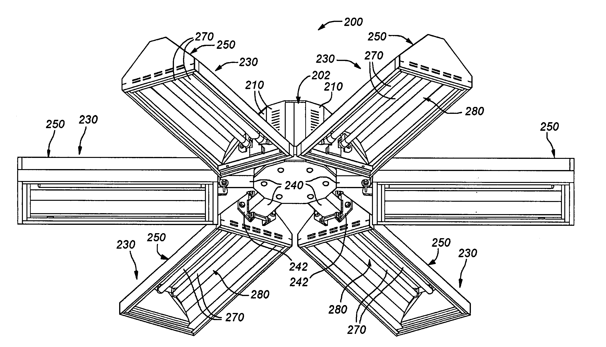
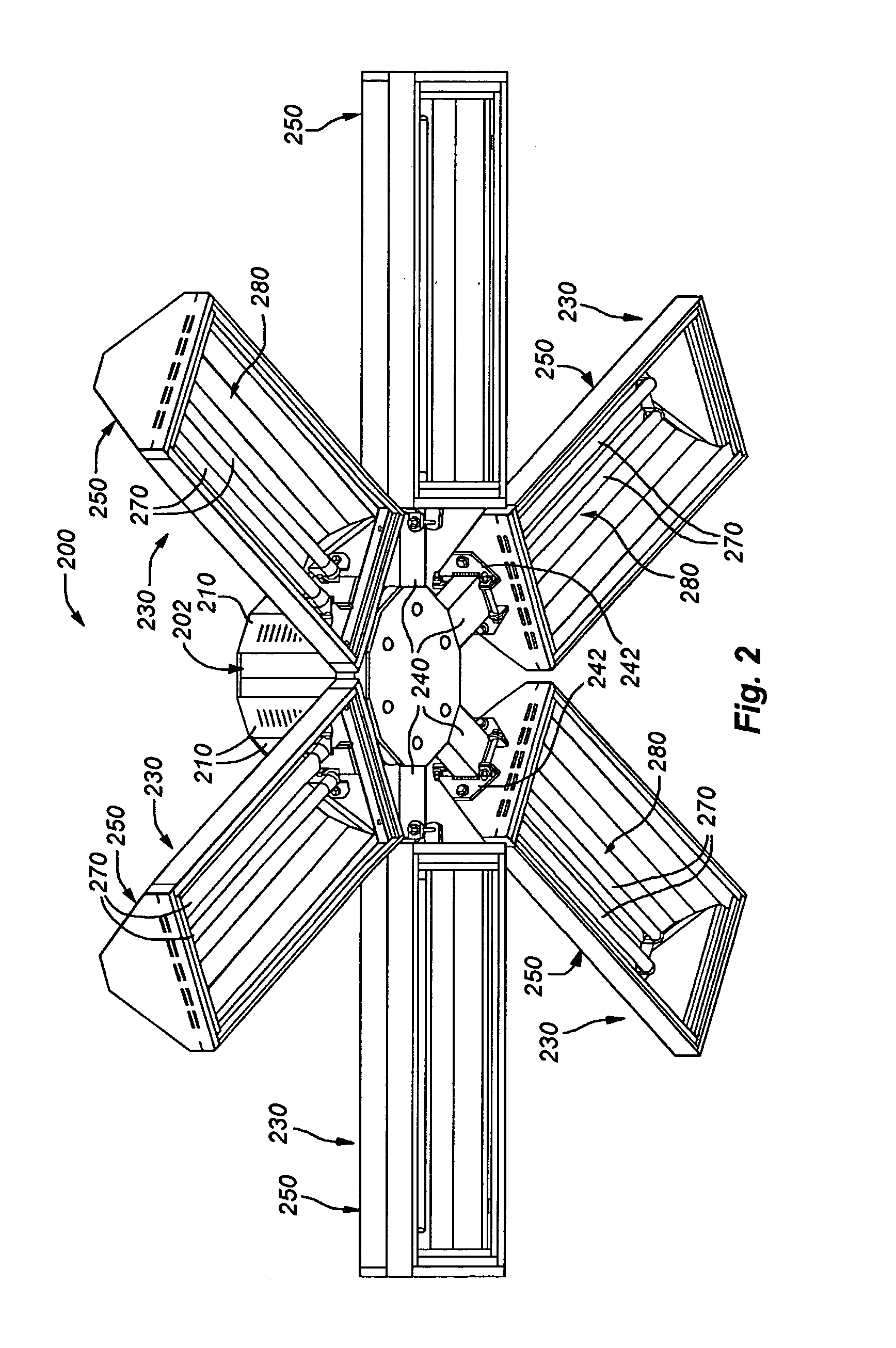
[0025]FIG. 2 shows an adjustable, high-output, multi-arm, industrial lighting fixture 200 according to an embodiment of this invention. The fixture 200 consists of a center housing 202 that is shown in greater detail in FIG. 3. The center housing 202 includes a mounting hook 204 adjacent a center point or axis 205 along its top surface 206. The hook 204 can be interconnected with a conventional chain or cable (not shown) for mounting to a ceiling or supporting beam, as required. An appropriate power cable (also not shown) can travel along this chain from the top 206 of the center housing 202 to a junction box in the building. The center housing 202 is constructed from conventional sheet metal having a thickness of between approximately 1 / 32 and 1 / 8 inch in typical embodiments. However, size and strength dictate the exact thickness of the metal or other sheet material (plastic, for example) used in connection with the fixture of this invention. The side walls of the center housing 20...


PUM


Abstract

This invention provides a high-output industrial light fixture that employs a plurality of commercially available fluorescent light sources in an array of adjustable arm assemblies each housing one or more light sources (fluorescent bulbs) in an associated reflector box or other source housing structure. By adjusting the arm assemblies, a more-precise spread of light onto the target surface can be achieved. Arm mounting brackets can be provided with one or more locking positions to facilitate multi-position angular placement of each individual arm. A plurality of arm assemblies can be provided around a center housing or hub, each directed outwardly in a radial direction from a central point or axis of the center housing/hub. Each arm's source reflector box/source housing structure can be located to project light either downwardly or upwardly and can be angled at a plurality of angular adjustment positions with respect to the center housing in each of the upward and/or downward positions. The bottom surface of center housing remains unobstructed (with arm assemblies extending away from it) so that cameras, sensors and other devices can be provided thereon. In an alternate embodiment, the reflector box/source housing structure for containing each light source can be mounted so as to extend transversely to a radial direction from the center. Accordingly, each box is located at a radial spacing from the center and extends substantially perpendicularly with respect to the radius, so as to define a polygon of reflector boxes around the center.

Description

BACKGROUND OF THE INVENTION[0001]1. Field of the Invention[0002]This invention relates to industrial lighting and, more particularly, to high-output lighting fixtures using fluorescent lighting sources.[0003]2. Background Information[0004]High-output lighting fixtures are used in a variety of indoor and outdoor applications. Notably, a large unobstructed volume, such as a warehouse or indoor arena may employ a significant number of fixtures, which depend from the roof or supporting beams at predetermined spacing, in order to create a desired lighting effect. The fixtures often used for this purpose are metal-halide bulb fixtures, such as the exemplary fixture 100 shown in FIG. 1. Such metal-halide fixtures typically include a base 102 attached to one end of a chain or cable 104, with the chain's opposing end (not shown) secured to the building's roof or an associated support beam. The exemplary fixture base 102 includes a mounting socket 106 for a single large metal-halide bulb 110....

Claims


Application Information

Patent Timeline
IPC IPC(8): F21S8/06F21S4/00
CPCF21S2/005F21S8/065F21V21/30F21V14/02F21V33/0052F21V33/0076F21Y2103/00F21Y2113/00
Inventor EDWARDS, JR., RICHARD D.
Owner EDWARDS ENTERPRISES
Why Eureka
Try Eureka