Apparatus and method for protecting an uninterruptible power supply and critical loads connected thereto

a technology of uninterruptible power supply and apparatus, applied in emergency power supply arrangements, power network operation system integration, instruments, etc., can solve problems such as affecting the operation of all equipment, including critical loads, and affecting the backup power system. , to achieve the effect of reducing the battery tim

Inactive Publication Date: 2006-11-07
LIEBERT
View PDF7 Cites 25 Cited by
  • Summary
  • Abstract
  • Description
  • Claims
  • Application Information

AI Technical Summary

Benefits of technology

[0009]One aspect of a system constructed in accordance with certain teachings of this disclosure is the protection of a backup power source, e.g., a UPS, and the loads being powered thereby from overload damage or decreased battery time caused by users plugging non-critical equipment into the critical circuits. A system and method in accordance with certain other teachings of the present disclosure may also be constructed to protect the UPS and the equipment in the event of an equipment failure, e.g., a short circuit or an over current condition.

Problems solved by technology

Problems have been observed in such installations in that various users of such facilities may inadvertently compromise the backup power system.
Although new systems are started up in an optimal state contemplated by the facility design engineers, over time it is likely that the overall critical electrical system will change without regard for the critical equipment.
When unnecessary equipment is installed on critical circuits, the overall impact of any single device being placed on the system may be considered non-invasive, but the additive effect of the overloads can jeopardize the operation of all equipment, including the critical loads, if the UPS system is overloaded.
Ultimately, these situations result in interrupted operations that result in revenue losses for the facility.
At present, there is no system available that allows for monitoring and protection of a number of critical electrical systems at a single location or for monitoring a single system at various locations, thus providing additional impetus for the system described herein.

Method used


Image

  • Apparatus and method for protecting an uninterruptible power supply and critical loads connected thereto
  • Apparatus and method for protecting an uninterruptible power supply and critical loads connected thereto
  • Apparatus and method for protecting an uninterruptible power supply and critical loads connected thereto

Examples


Embodiment Construction

[0019]Although the following description is in terms of a control and protection system for a UPS installed in a retail environment, it will be understood by those skilled in the art that it is applicable to control and protection of all types of backup power or other critical circuits in various types of installations.

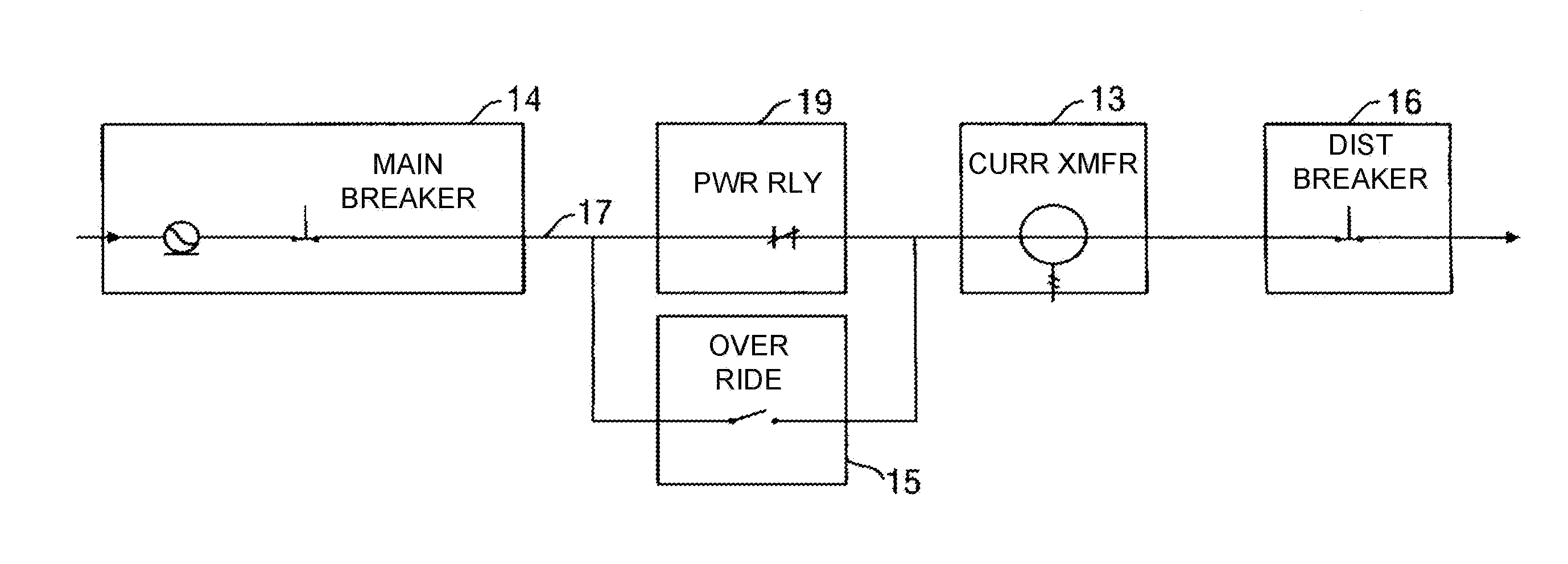
[0020]The control and protection system described herein (the “Load Manager”) is designed for the purpose of protecting a UPS from unexpected loads, as well as keeping critical loads operational when anomalies appear within the power system. The Load Manager also possesses the capability to provide “load shedding” during power outages. This feature allows devices attached to non-critical circuits to be disconnected to conserve UPS battery life and extend the operation window of the critical equipment.

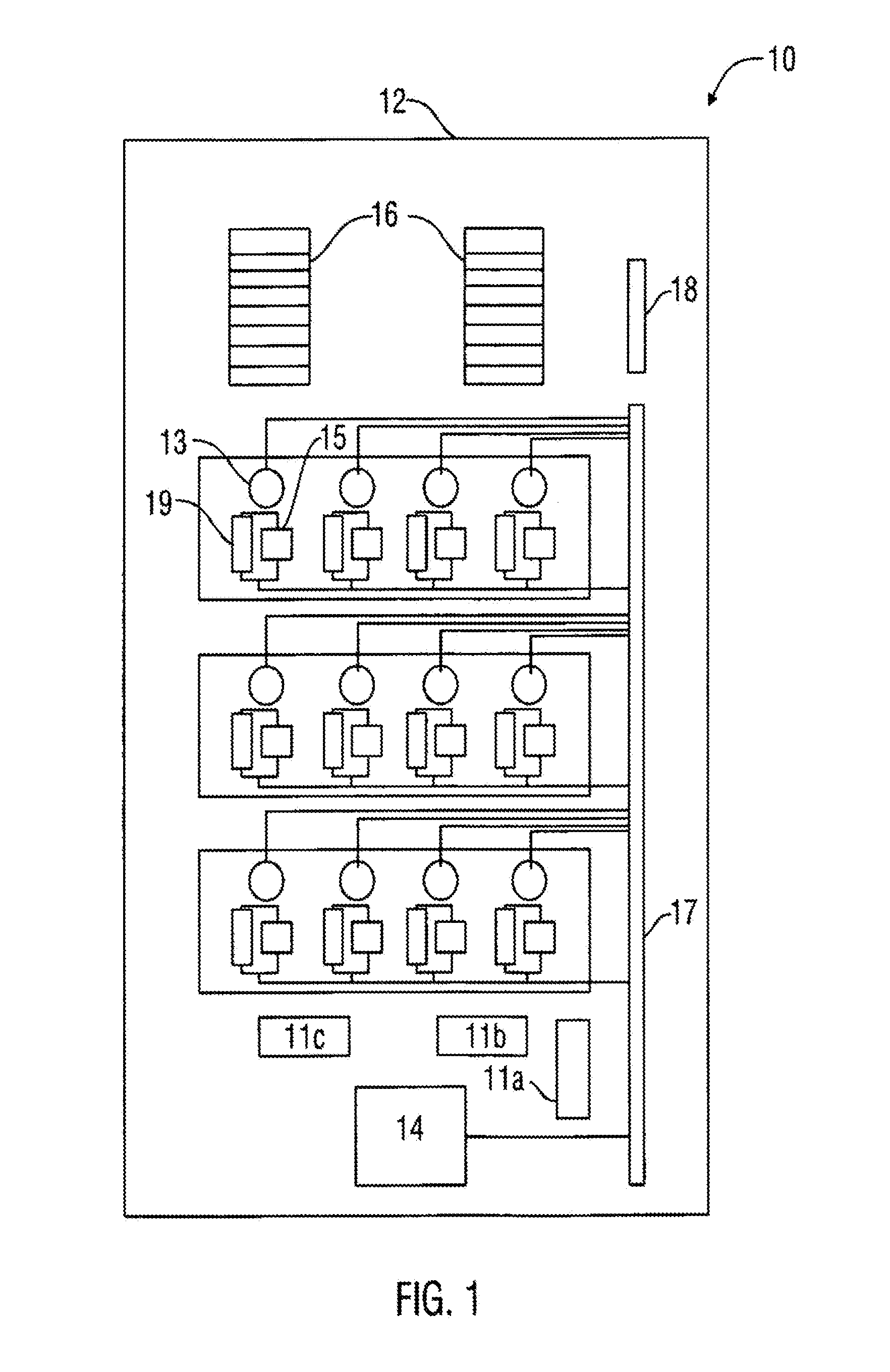
[0021]Physical construction of the Load Manager is illustrated in FIG. 1. In one embodiment, the Load Manager 10 can be constructed in the basic form of a standard electr...


PUM


Abstract

An apparatus and method for monitoring and controlling a backup power source and one or more critical loads powered thereby is disclosed. The apparatus is constructed in the form of an electrical distribution panel that includes electronic systems for monitoring the current to the critical loads. In the event of an overcurrent condition on one or more critical load circuits, the system is able to disable power flow to the offending circuit so as to protect the remaining critical load circuits and the backup power source. The system is also provided with a means for communicating status information about the system to a remote user.

Description

[0001]This application claims the benefit of U.S. Provisional Application No. 60 / 486,303 filed Jul. 11, 2003.FIELD OF THE INVENTION[0002]The present invention relates to the provision of backup power and line protection for critical electrical loads. Specifically, the invention relates to various aspects of monitoring the power supplied by a backup power source (e.g., an uninterruptible power supply) and controlling the loads to which the UPS supplies power so as to ensure a reliable source of backup power to the critical loads.BACKGROUND OF THE INVENTION[0003]In various applications certain electrical loads are critical to the mission of the facility. To illustrate, in the case of retail establishments, an example of such critical loads are the network of computers that provide for the retailers point of sale (POS) system. Other types of facilities such as industrial production facilities or hospitals have other types of critical loads. To minimize the disruption to the operation o...

Claims


Application Information

Patent Timeline
Patent Type & Authority Patents(United States)
IPC IPC(8): G08B21/00
CPCH02J3/14H02J9/002H02J9/062Y02B70/3225Y02B70/3233Y02B70/3291Y04S20/222Y04S20/225Y04S20/248Y02B70/30H02J2310/60Y04S20/20
Inventor ZIEJEWSKI, STEVEN J.HURST, JR., ERNEST P.
Owner LIEBERT
Why Eureka
Try Eureka