Liquid crystal display including array of protrusions in a broken zigzag pattern all formed within area of light-shielding matrix

a technology of liquid crystal display and array of protrusions, applied in non-linear optics, instruments, optics, etc., can solve the problems of significant masking of the deteriorating display quality, disordered orientation of liquid crystal molecules, and dislocation around the edges of breaks

Inactive Publication Date: 2006-11-07
INNOLUX CORP
View PDF15 Cites 20 Cited by
  • Summary
  • Abstract
  • Description
  • Claims
  • Application Information

AI Technical Summary

Benefits of technology

[0007]It is an object of the present invention to provide a multi-domain vertically aligned (MVA) LCD having d

Problems solved by technology

However, since the pattern of the first protrusions is discontinuous, the orientation of the liquid crystal molecules is disordered at the edges of the breaks.
This results in disclination generating around the edges of the breaks

Method used


Image

  • Liquid crystal display including array of protrusions in a broken zigzag pattern all formed within area of light-shielding matrix
  • Liquid crystal display including array of protrusions in a broken zigzag pattern all formed within area of light-shielding matrix
  • Liquid crystal display including array of protrusions in a broken zigzag pattern all formed within area of light-shielding matrix

Examples


first embodiment

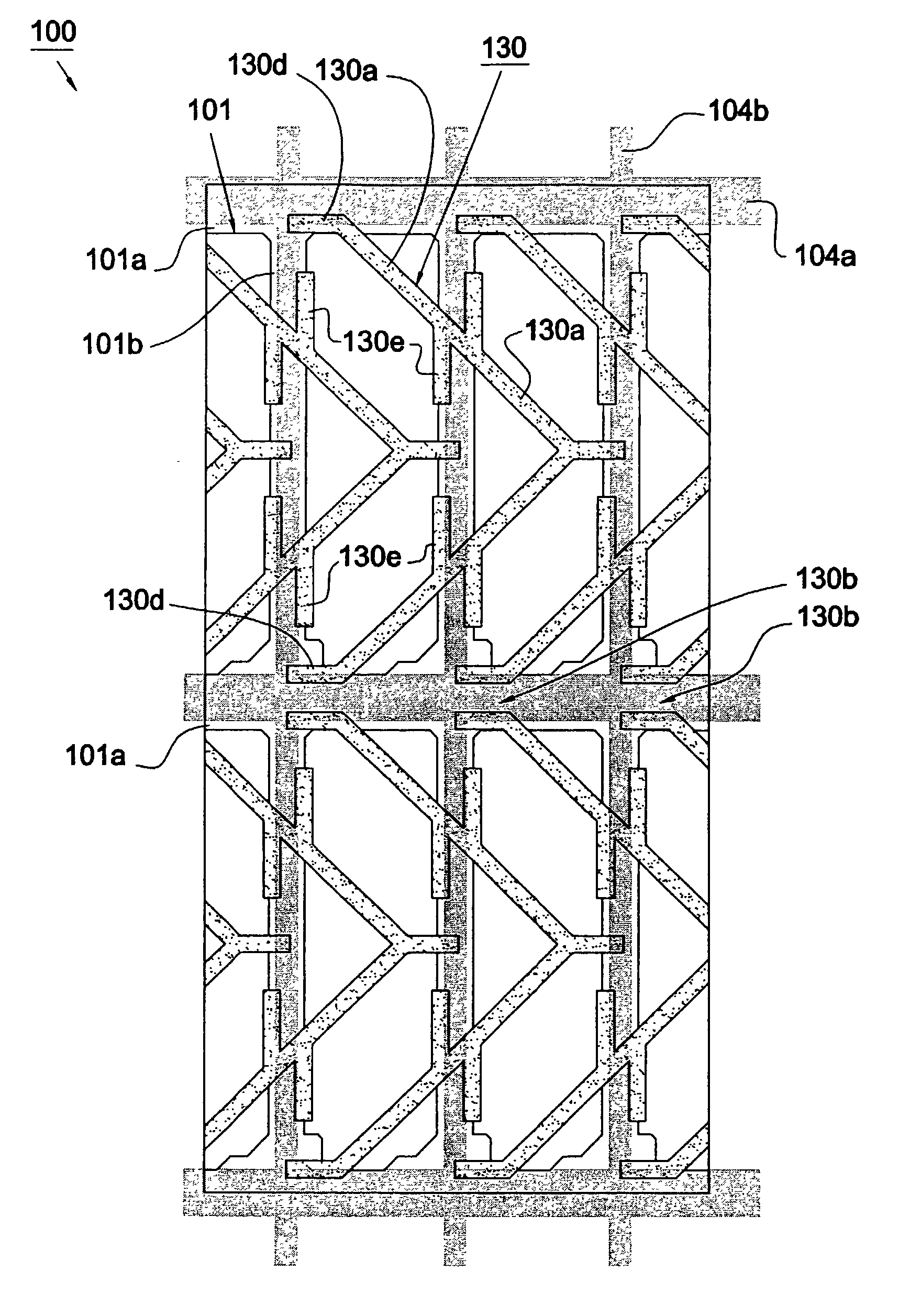
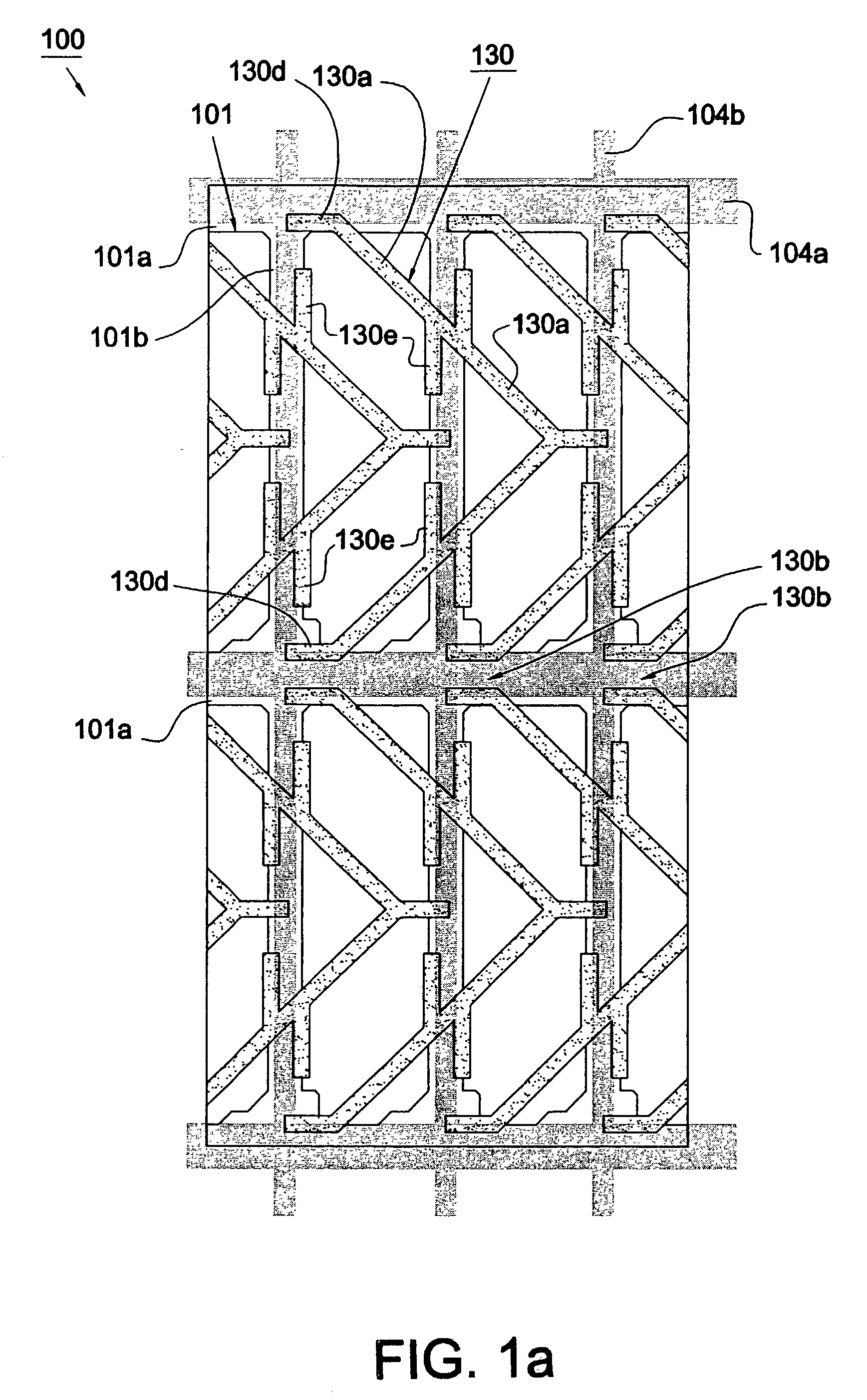
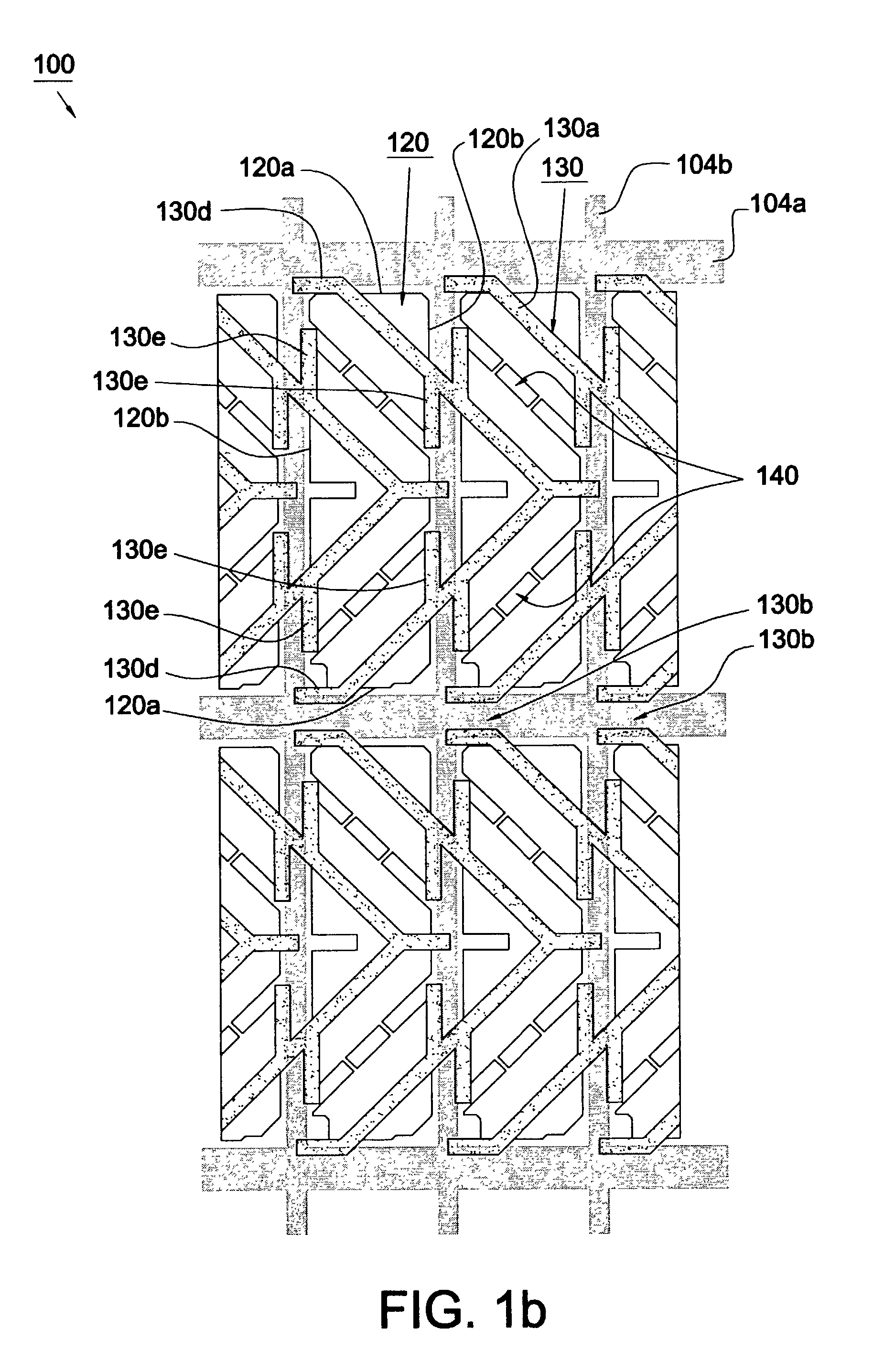
[0024]FIGS. 1a and 1b show a portion of an MVA LCD 100 with discontinuous regulating means realized by providing specific protrusion and slit pattern according to the present invention. The first substrate 102 has a light-shielding matrix 101 (not shown in FIG. 1b), for example a black matrix, formed thereon. The second substrate 104 is provided with a plurality of parallel gate lines 104a, a plurality of parallel data lines 104b perpendicular to the gate lines 104a, and a plurality of thin film transistors (TFTs) and pixel electrodes 120 (not shown in FIG. 1a) formed like a matrix at the intersections between the gate lines 104a and data lines 104b. The pixel electrode 120 has first edges 120a parallel to the gate lines 104a and second edges 120b parallel to the data lines 104b. The LCD 100 is formed with a plurality of protrusions 130 and slits 140 (not shown in FIG. 1a) for regulating the orientation of the liquid crystal such that the alignment of liquid crystal molecules is ind...

second embodiment

[0028]FIG. 2 shows the pixel region of an MVA LCD 200 according to the present invention wherein the pixel electrodes 120 and the slits 140 are not shown. This LCD 200 includes a plurality of protrusions 132 formed inside one channel defined by two first branches 130d extending from the main bodies 130a of adjacent protrusions 130 and the substrates 102, 104 (not shown). During the step of pressing the substrates in the ODF process, the protrusions 132 slow down the flow rate of the dropped liquid crystal material through the aformentioned channel defined by the first branches 130d.

third embodiment

[0029]FIG. 3 shows the pixel region of an MVA LCD 300 according to the present invention wherein the pixel electrodes 120 and the slits 140 are not shown. This LCD 300 includes a plurality of protrusions 134 formed at a location close to the left opening of the aformentioned channel. During the step of pressing the substrates in the ODF process, the protrusions 134 slow down the flow rate of the dropped liquid crystal material through the aformentioned channel.


PUM


Abstract

A liquid crystal display mainly includes two substrates processed for vertical alignment and a liquid crystal having a negative dielectric constant anisotropy sealed between the two substrates. An array of slits is provided on pixel electrodes formed on one substrate. A light-shielding matrix and an array of protrusions is provided on the other substrate. Each of the first protrusions has a main body being arranged substantially in a zigzag pattern and in parallel to one another. The slits and the main bodies of the first protrusions are arranged alternately. The liquid crystal display is characterized in that the first protrusions have a plurality of breaks formed within the area of the light-shielding matrix.

Description

BACKGROUND OF THE INVENTION[0001]1. Field of the Invention[0002]The present invention generally relates to a liquid crystal display (LCD), and more particularly to a multi-domain vertically aligned (MVA) LCD having specific protrusion pattern for use in a one drop fill (ODF) process.[0003]2. Description of the Related Art[0004]Liquid crystal display mainly comprises two oppositely positioned first and second substrates and a liquid crystal layer interposed therebetween. U.S. Pat. No. 5,263,888 discloses a one drop fill (ODF) process comprising the steps of applying an adhesive onto the entire periphery of the first substrate, dropping the liquid crystal material to the first substrate, superposing the second substrate upon the first substrate and pressing the substrates until a gap between the substrates reaches a predetermined value (typically 3–10 micrometers), and curing the adhesive. In the step of pressing the substrates, the liquid crystal material spreads to fill the space be...

Claims


Application Information

Patent Timeline
IPC IPC(8): G02F1/1337G02F1/1333G02F1/139
CPCG02F1/133707G02F1/1393
Inventor LIN, BI LY
Owner INNOLUX CORP
Why Eureka
Try Eureka