

Pole tip with sides flared at media-facing surface
a technology of pole tip and media-facing surface, which is applied in the field of electromagnetically-transducers, can solve the problem of becoming more difficult to transmit high-intensity magnetic flux through the pole tip surface, and achieve the effect of increasing magnetic flux and improving density
- Summary
- Abstract
- Description
- Claims
- Application Information
AI Technical Summary
Benefits of technology
Problems solved by technology
Method used
Image

Examples
first embodiment
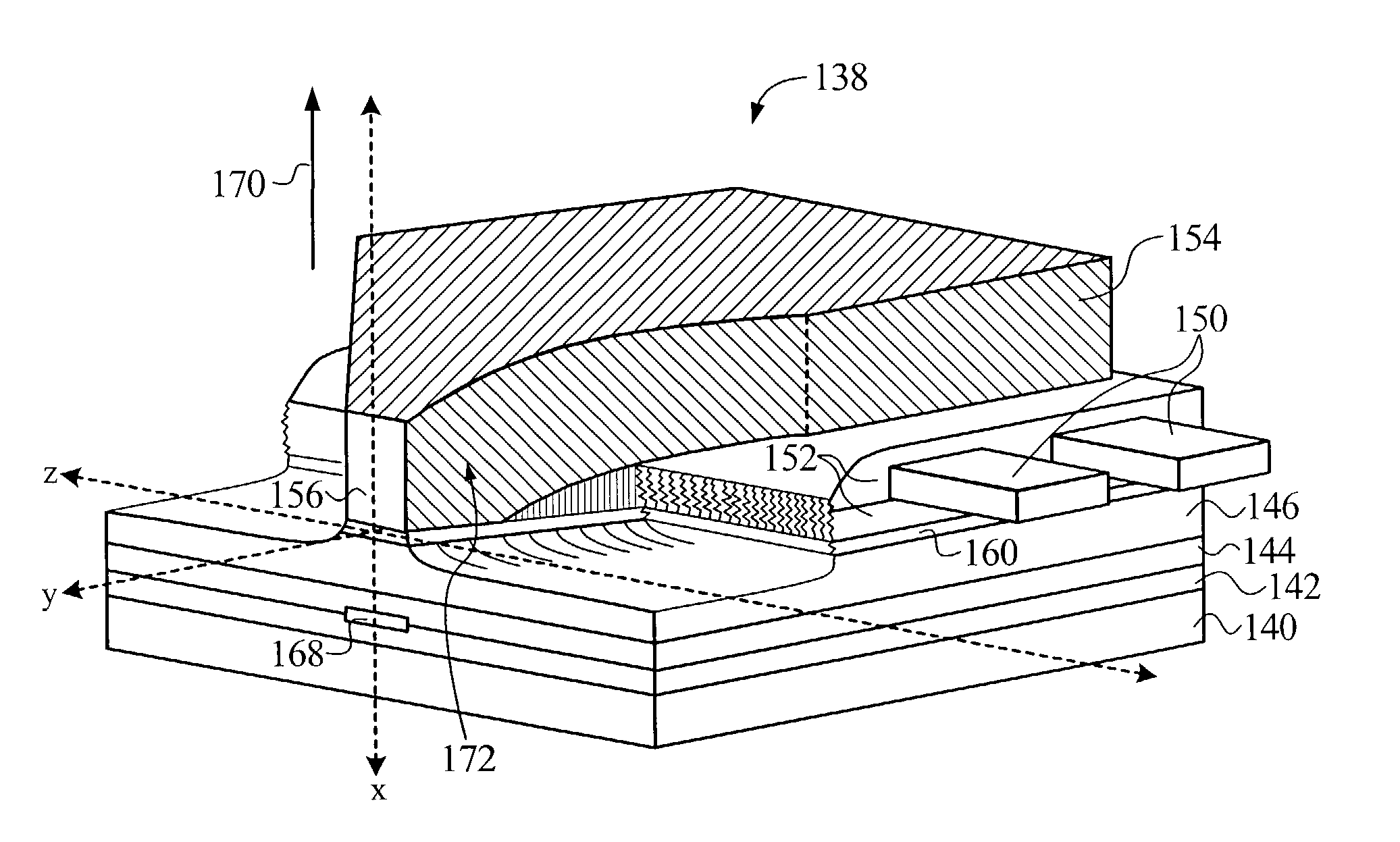
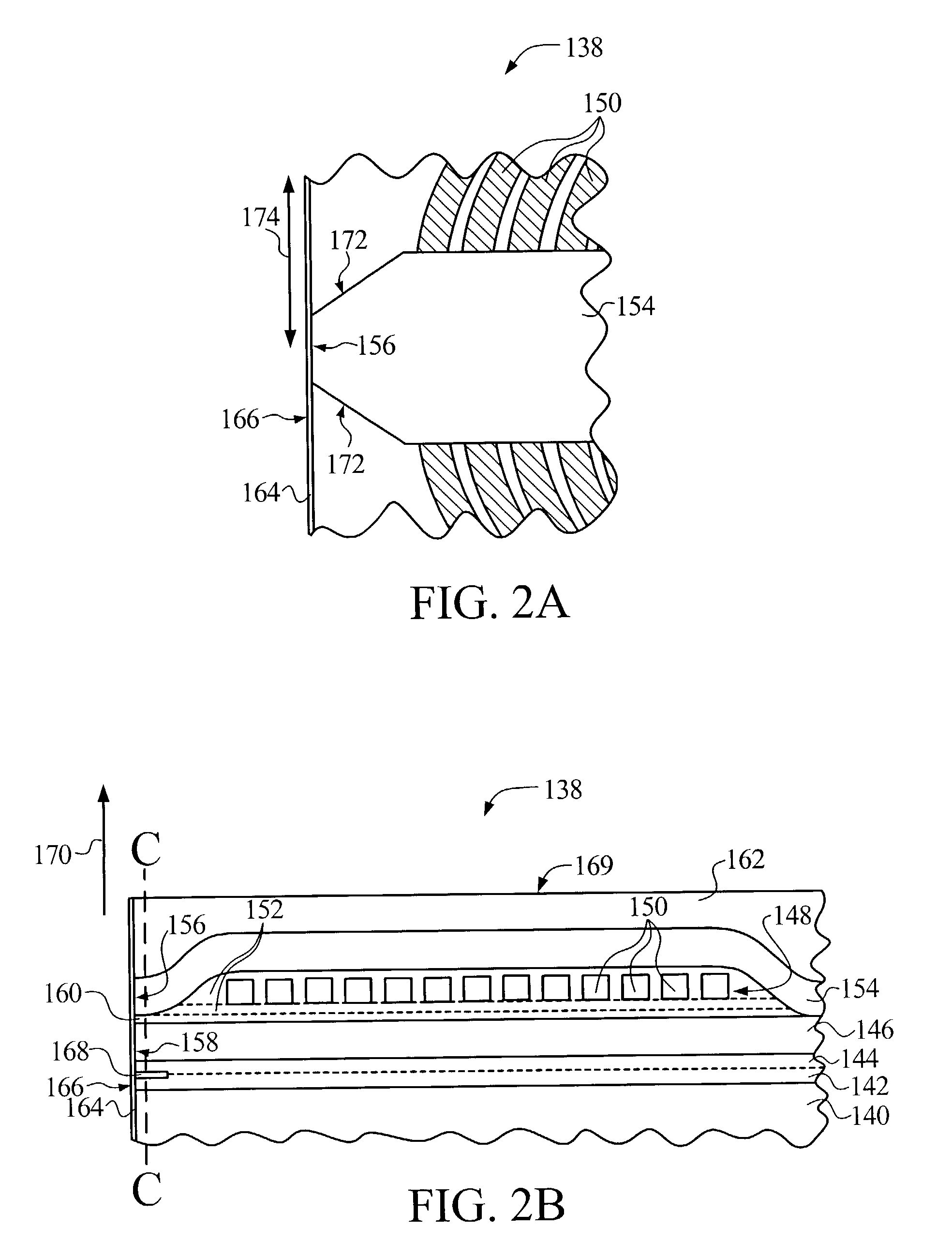
[0030]FIG. 2B depicts a first embodiment in accordance with the present invention and shows a cutaway cross-sectional view of a merged inductive and magnetoresistive (MR) transducer 138 of a read / write head. Transducer 138 has been formed in a plurality of adjoining solid layers on a wafer substrate, not shown. A first magnetically soft shield layer 140 has been formed adjacent to the wafer substrate. A first layer of nonmagnetic, electrically insulating material 142 is disposed on the shield layer 140, adjoining an MR sensor 168. The MR sensor 168 can be any sensor that utilizes a change in resistance associated with a change in magnetic field to sense that field, which may be measured as a change in current or voltage across the sensor, as the sensor passes over a track on a medium upon which information is stored.
[0031]A second layer of nonmagnetic, electrically insulating material 144 is disposed between MR sensor 168 and a second magnetically soft shield layer. The shield layer...
third embodiment
[0032]An electrically conductive coil layer 148 has coil sections 150 that are separated from the leading pole layer 146 by additional nonmagnetic, electrically insulating material 152. The coil sections 150 are substantially parallel in the cross-section shown, and coil layer 148 spirals about a magnetically soft back gap stud, not shown, extending away from a media-facing surface 166 in an area outside that shown in FIG. 2B. Additional coil layers may optionally be formed, for example, as shown in a third embodiment in FIG. 5.
[0033]A second or trailing pole layer 154 is curved to cover the insulating material 152 while also nearly adjoining the leading pole layer 146 adjacent to a media-facing surface 166. The trailing pole layer 154 is coupled to a back gap stud, not shown, so that leading pole layer 146, the back gap stud and trailing pole layer 154 form a magnetic loop substantially encircling and electrically isolated from coil sections 150. The pole layers have substantially ...
second embodiment
[0050]FIG. 4A depicts the present invention. This embodiment includes a magnetically soft trailing pedestal 180 between the trailing pole layer 154 and the trailing pole tip surface 156. Trailing pedestal 180 is coupled to trailing pole layer 154, a back gap stud, not shown, and leading pole layer 146 to form a magnetic loop substantially encircling and electrically isolated from coil sections 150. The trailing pole tip surface 156 lies on the trailing pedestal 180 and is magnetically coupled to the leading pole tip surface 158; the two pole tip surfaces are separated by a submicron nonferromagnetic gap layer 160.
[0051]FIG. 4B is a cutaway, opened-up view of the transducer 138 of FIG. 4A showing the coil sections 150 depicted with hash marks. Non-parallel, diverging sides 182 of the trailing pedestal 180 are shown that are perpendicular to the submicron gap layer, but not to the media-facing surface. The sides 182 diverge from each other in the track width dimension 174 the farther ...
PUM
| Property | Measurement | Unit |
|---|---|---|
| thickness | aaaaa | aaaaa |
| angle | aaaaa | aaaaa |
| angle | aaaaa | aaaaa |
Abstract
Description
Claims
Application Information