Method for controlling the speed of a vehicle

a technology for controlling the speed of a vehicle and the transmission, which is applied in the direction of process and machine control, braking systems, instruments, etc., can solve the problems of unrealized adjustment of such a drive torque, unwound adjustment of engine torque, and increase of engine torque when downshifting the transmission, so as to ensure the economical operation of the vehicle, reduce the deviation of control, and increase the overrun torque

Inactive Publication Date: 2006-11-07
ROBERT BOSCH GMBH
View PDF21 Cites 9 Cited by
  • Summary
  • Abstract
  • Description
  • Claims
  • Application Information

AI Technical Summary

Benefits of technology

[0003]The method of the invention for controlling the speed of a vehicle affords the advantage with respect to the foregoing that, for the control of the speed of the vehicle, an actual speed is caused to track a desired speed. A transmission of the vehicle is driven for downshifting to reduce the actual speed. With the downshifting of the transmission, a larger transmission ratio of the transmission results and a larger overrun torque, in magnitude, is achieved. In this way, an effective relief of the brake system is realized. A relief of load of this kind reduces not only the wear of the brake system but also avoids an overheating of the brakes especially in downhill travel over a longer distance.
[0004]To utilize the overrun torque, an overrun switchoff is furthermore ensured at higher engine rpms and therefore a more economical operation of the vehicle is ensured. A further advantage of the method of the invention results also for vehicle speed controllers or adaptive vehicle speed controllers without brake intervention. In this case, the downshifting and the larger overrun torque, in magnitude, associated therewith effects a reduced control deviation between the actual speed and the desired speed, for example, during downhill travel.
[0005]When the transmission, in addition to driving a brake of a vehicle is driven to reduce the actual speed, then, in addition to the relief of the brake, also an overall greater braking action and therefore a more effective and more rapid reduction of the actual speed is realized for tracking the desired speed.
[0006]It is especially advantageous that the transmission is driven to downshift when the output quantity of the drive unit, which is requested by the control, drops below a second value which is expected to adjust for the overrun operation in the next lower transmission stage. In this way, the downshift is only carried out when the value for the output quantity, which results in the next lower transmission stage, for example, the corresponding overrun torque, can be used completely for reducing the actual speed. If the drive torque is viewed as the output quantity of the drive unit, then it is therefore not necessary to adjust a drive torque which lies between the overrun torques of two mutually adjacent gear stages. The adjustment of such a drive torque can not be realized without adapting the engine torque. A change of the engine torque, for example, an increase of the engine torque when downshifting the transmission can, however, be unwanted especially during a braking phase. Such a change of the engine torque and therefore the adjustment of a drive torque between the overrun torques of two mutually adjacent gear stages is, however, prevented when the transmission is driven only then for downshifting when the output quantity of the drive unit, which is requested by the control, drops below the second value which is expected to adjust for the overrun operation in the next lower transmission stage. In the case of the additional drive of a brake of the vehicle for reducing the actual speed, an output quantity, which is requested by the control and which lies between the values of two mutually adjacent transmission stages, can be realized only by a corresponding drive of the brake and an adjustment of the brake action. The overrun torque of the instantaneous gear stage can be used without having to change the engine torque.
[0008]A further advantage is that the transmission is driven to downshift in dependence upon an accelerator pedal value and that the accelerator pedal value is iteratively increased for a requested downshift of the transmission. This solution is especially simple to execute and is especially useful in the case wherein the vehicle speed control is realized on the basis of torque requests and therefore the time point for the downshift is defined in that the drive torque, which is requested by the vehicle speed control or the adaptive speed control, corresponds to the overrun torque of the next lower gear stage or transmission stage.
[0009]A further advantage is that the accelerator pedal value is changed in dependence upon a difference between an initial deceleration request with the activation of the brake system and an instantaneous deceleration request to the brake system. This solution is, in turn, especially suitable for the case wherein the vehicle speed control or the adaptive vehicle speed control is realized not on the basis of the torque requests but on the basis of acceleration requests or deceleration requests. Compared to the previously described time criterion, this solution affords the advantage that this solution makes the change of the accelerator pedal value and therefore, if required, the initiation of a downshift of the transmission dependent upon the actual deceleration requests to the brakes and therefore in dependence upon the instantaneous driving situation whereby the downshift time point can be optimized.

Problems solved by technology

The adjustment of such a drive torque can not be realized without adapting the engine torque.
A change of the engine torque, for example, an increase of the engine torque when downshifting the transmission can, however, be unwanted especially during a braking phase.

Method used


Image

  • Method for controlling the speed of a vehicle
  • Method for controlling the speed of a vehicle
  • Method for controlling the speed of a vehicle

Examples


first embodiment

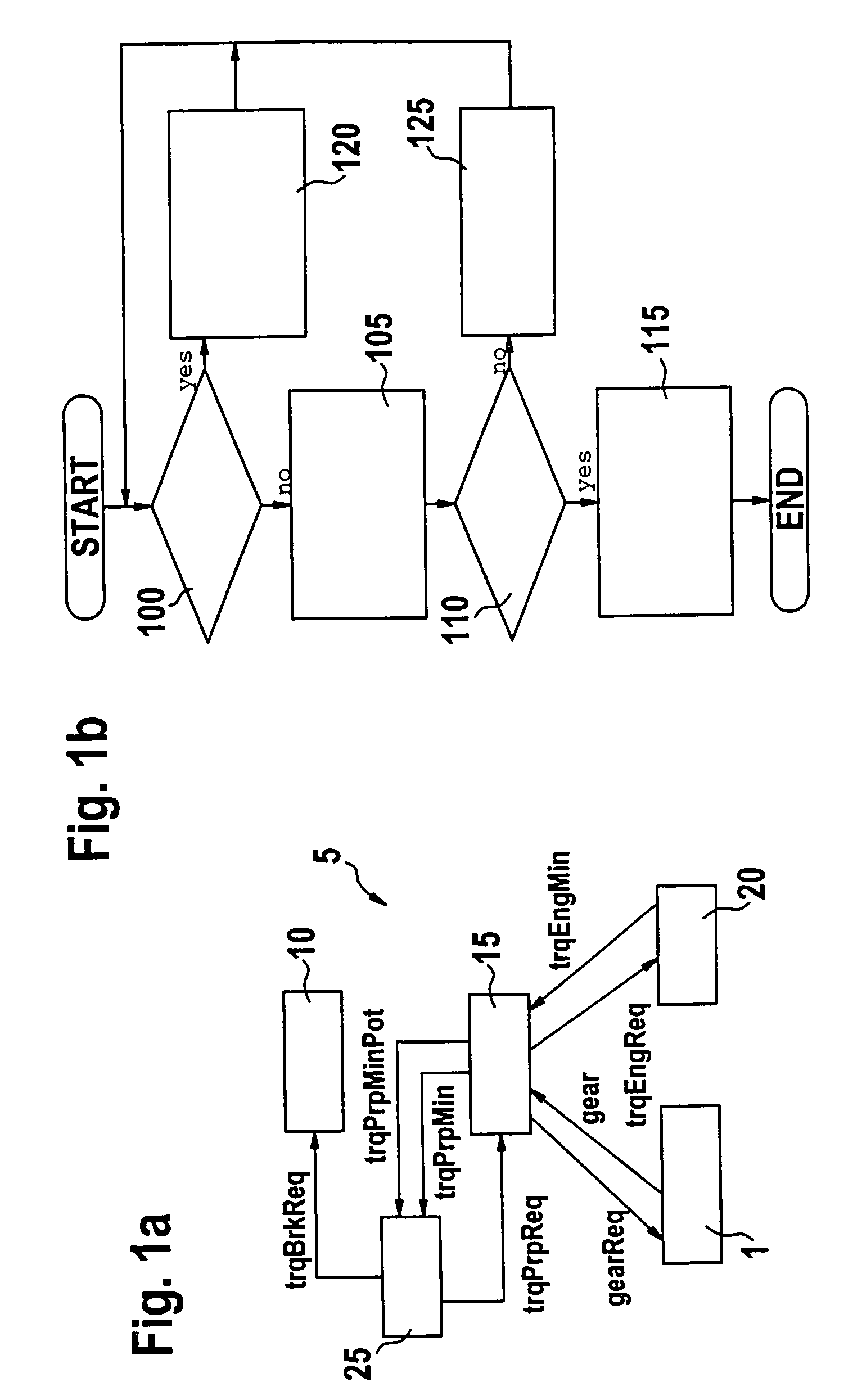
[0023]In the following, and with reference to the flowchart of FIG. 1b, the sequence of the method of the invention for FIG. 1a is described. After the start of the program, the vehicle speed controller 25 checks at program point 100 whether the desired value trqCrCtReq for the resulting drive torque, which is requested by the vehicle speed controller 25, is greater than the overrun torque trqPrpMin of the drive unit 15 in the instantaneous gear (gear). If this is the case, then the program branches to program point 120; otherwise the program branches to a program point 105.

[0024]At program point 105, the vehicle speed controller 25 detects a so-called braking case wherein the actual speed must be reduced in order to track the actual speed to the desired speed. Here, the vehicle speed controller 25 sets the desired value trqPrpReq for the drive torque equal to the overrun torque trqPrpMin in the instantaneous gear (gear) and the desired value trqBrkReq for the brake torque as follow...

second embodiment

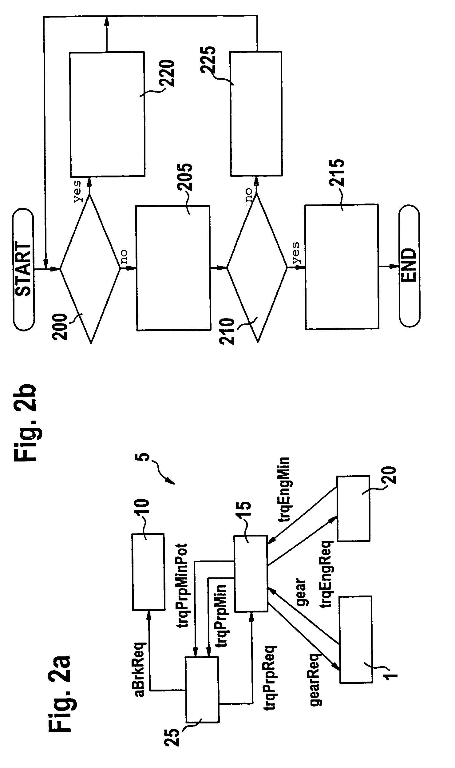
[0030]Except for the described torque interface to the brake system 10, there is also the possibility of an acceleration interface according to FIG. 2a wherein the same reference numerals identify the same elements as in FIG. 1a and, with respect to FIG. 1a, changes are only with respect to the interface between the vehicle speed controller 25 and the brake system 10. In lieu of a desired value for the brake torque, the vehicle speed controller 25 requests in an example of FIG. 2a a brake deceleration from the brake system 10. This desired value for the brake deceleration is identified as aBrkReq. In this case, the vehicle speed controller 25 has no data as to the brake torque to be developed by the brake system 10. In this way, for the embodiment of FIG. 2a, a changed flowchart according to FIG. 2b results. After the start of the program, a check is made by the vehicle speed controller 25 at program point 200 as to whether the desired value trqCrCtReq for the resulting drive torque...

third embodiment

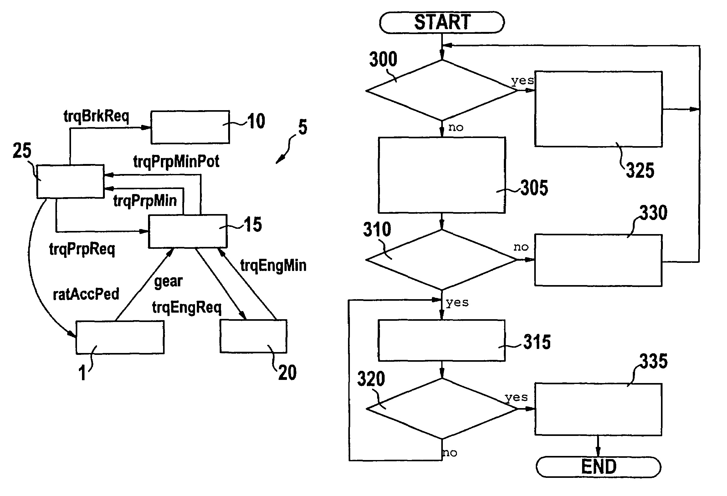
[0037]A further variation or embodiment is obtained when using a transmission control for the transmission 1 which permits no direct gear input via the drive unit 15; instead, the transmission control itself inputs the gear to be set in dependence upon a virtual accelerator pedal angle ratAccPed and further parameters which can vary depending upon the manufacturer of the transmission control apparatus. As additional parameters, the engine rpm (n) and an engine torque at full-load operation or at part-load operation can be applied in a manner known per se. Up to now, such a virtual accelerator pedal is utilized only for requesting a downshifting for a propulsion request and, in the braking case, is usually set unused to zero. According to the invention, in FIGS. 3a and 3b, it is provided to achieve a downshifting by inputting a high value for the accelerator pedal angle.

[0038]In the embodiment of FIG. 3a, the same reference numerals identify the same elements as in the first embodime...


PUM


Abstract

A method is directed to the control of the speed of a vehicle wherein the actual speed is caused to track the desired speed. For reducing the actual speed, a transmission (1) of the vehicle (5) is driven to downshift and thereby the brake system is protected with respect to wear and overheating.

Description

RELATED APPLICATION[0001]This application claims priority of German patent application 102 51 563.8, filed Nov. 6, 2002, the entire contents of which is incorporated herein by reference.BACKGROUND OF THE INVENTION[0002]Modern driver assistance systems are known which, for example, include a vehicle speed controller or an adaptive vehicle speed controller having brake intervention. These vehicle speed controllers can drive a drive unit as well as a brake system of a vehicle via suitable interfaces. Here, it must be avoided as best as possible that brake system and drive unit operate in opposition to each other. For this reason, a brake intervention via the vehicle speed controller is not enabled when there is a drive of the drive unit with a drive torque which is greater than the minimum possible drive torque referred to the instantaneous gear. In active brake control via the vehicle speed controller, the minimum possible drive torque referred to the instantaneous gear is requested b...

Claims


Application Information

Patent Timeline
Patent Type & Authority Patents(United States)
IPC IPC(8): G06F7/00G06F17/00B60T7/12B60K31/04F16H61/02F16H61/21
CPCB60K31/04F16H61/21B60W2540/10B60W2540/12Y10T477/679F16H2061/0237F16H61/0213
Inventor GLORA, MICHAEL
Owner ROBERT BOSCH GMBH
Why Eureka
Try Eureka