Laced boot

a technology of laced boots and laced soles, which is applied in the field of laced boots, can solve the problems of limiting comfort, affecting circulation in the foot, and requiring a greater industrial cost, and achieves the effects of good comfort, simple manipulation, and good hold of the foo

Inactive Publication Date: 2006-11-14
GOODWELL INT
View PDF30 Cites 157 Cited by
  • Summary
  • Abstract
  • Description
  • Claims
  • Application Information

AI Technical Summary

Benefits of technology

[0010]The invention addresses the problem of improving the laced boot of the initially cited type in such a manner that a good hold of the foot is assured in the boot along with simple manipulation and good comfort and in particular a good heel hold.
[0017]The boot lace is preferably tightened by a tightening mechanism like the one known, e.g., from U.S. Pat. No. 2002 / 0095750 A1. This is a winding mechanism with a ratchet on whose winding mandrel both ends of the boot lace are wound. The boot lace is preferably a thin wire rope with high tensile strength and low bending resistance that can be easily wound on a winding mandrel with a small diameter.
[0018]The one-piece design of the boot lace also has the advantage that during certain movements of the foot certain sections of the boot lace are automatically tightened. If, for example the upper is bent forward, the above-cited second section becomes longer, which automatically entails a shortening of the first and of the third section so that as a result the heel is pressed more strongly downward and to the rear during an intensified frontal position and therewith pressure on the front edge of the snowboard.

Problems solved by technology

In order to achieve this, it would actually be necessary to made the boot upper relatively stiff for movements to the front and to the rear, relative to the longitudinal direction of the boot; however, this would limit the comfort, especially when walking.
However, such additional tightening straps necessitate a greater industrial expense and have the disadvantage in practice that the user, in order to have a good hold, tightens so strongly that the circulation in the foot is adversely affected.
This also has an adverse effect on the comfort and increases the danger of an accident.
Such a lacing is therefore not suitable for a boot with an upper surrounding part of the shinbone of the user.

Method used


Image

  • Laced boot
  • Laced boot
  • Laced boot

Examples


Embodiment Construction

[0027]This application claims priority from German application 103 11 175.1, filed Mar. 12, 2003, the entire disclosure of which is expressly incorporated herein by reference.

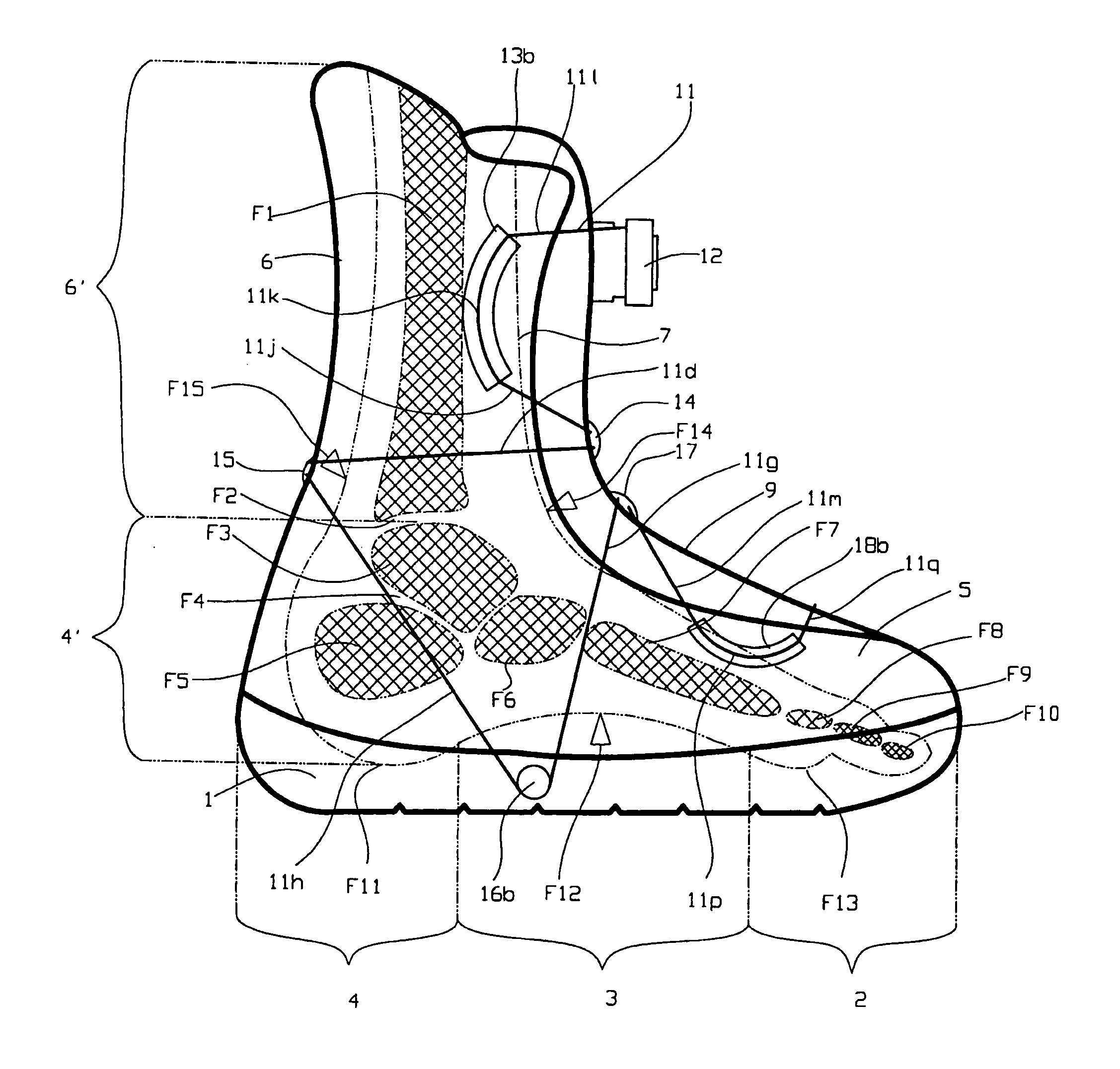
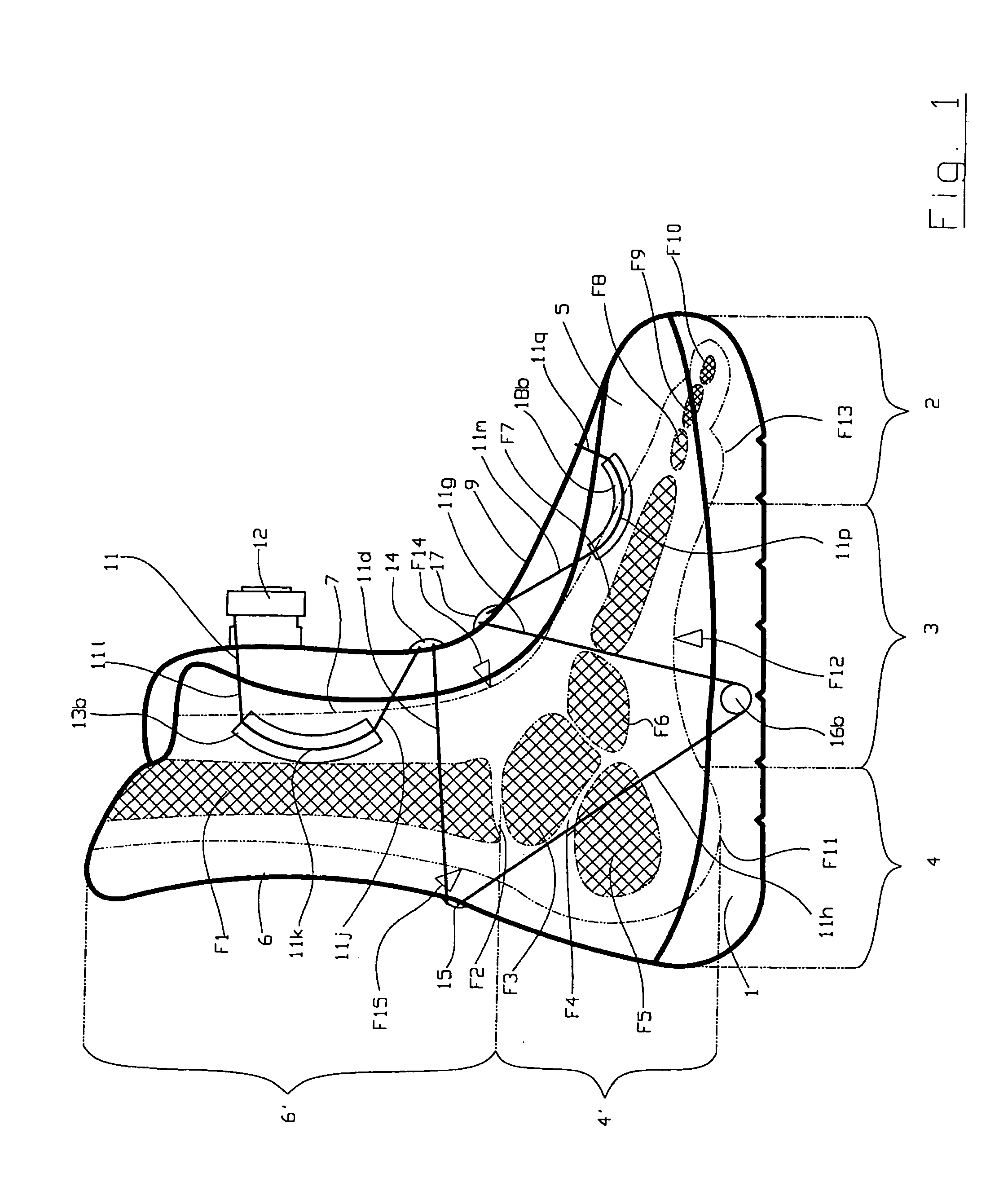
[0028]FIG. 1 is referred to at first, in which a foot F is schematically shown in a side view. The essential bones of the foot are shinbone F1 to which anklebone F3 is connected via upper ankle joint F2, followed, from the top downward, by heel bone F5 via lower ankle joint F4. Following lower ankle joint F4 the foot consists via navicular bone F6 and metatarsal bone F7 of toe bones, namely, a base toe member F8, a middle toe member F9 and a terminal toe member F10. Joints are also present between the last-named bones but are not shown. In the area of the foot sole a heel area F11 can be distinguished located below heel bone F5 and convexly curved to the outside in a lateral view, a metatarsal area F12 located below navicular bone F6 and below metatarsal bone F7 and concavely curved inward as well as a front fo...


PUM


Abstract

A laced boot having a boot lace and sections of the boot lace run in a continuous one-piece manner as follows: a first section runs from the metatarsal area of the sole over the instep of the boot; a second section runs from the metatarsal area of the sole around the outside of the upper above a heel area of the boot; and a third section runs from the same position of the upper to the instep and back to the cited position of the upper and the three named sections form a triangle, viewed from the side of the boot that covers the ankle joints of the foot.

Description

FIELD OF THE INVENTION[0001]The invention pertains to a laced boot.BACKGROUND OF THE INVENTION[0002]Laced boots such as snowboard boots, inline skate boots, hiking boots, mountain-climbing boots, etc. are laced by a boot lace threaded through several deflection elements such as, e.g., eyelets on two opposite tabs of the boot and the ends of the boot lace are fixed either by a lacing or by a holding and / or clamping device. Such a laced boot is known from EP 0 474 708 B1, WO 99 / 09850 A1 and DE 298 14 659 U1.[0003]Most laced boots and in particular snowboard boots are made of flexible material, which provides comfort and also allows a relatively great mobility of the user's foot which is especially desirable in the case of snowboarding. On the other hand, the connection between foot, boot and snowboard must be so firm that the rider can transfer the necessary forces onto the snowboard, especially onto its front and back edges. In order to achieve this, it would actually be necessary to...

Claims


Application Information

Patent Timeline
Patent Type & Authority Patents(United States)
IPC IPC(8): A43C11/00A43B5/04A43B23/02A43C1/04A43C11/16A43C11/20
CPCA43B5/0401A43B5/0447A43C1/04A43C11/16A43C11/20A43C11/165
Inventor ELKINGTON, MARKKOHLER, RALPH
Owner GOODWELL INT
Why Eureka
Try Eureka