Antenna for flat radio device

a radio device and antenna technology, applied in the structure of elongated active elements, resonant antennas, radiating elements, etc., can solve the problems of inconvenient general association with protruding structural elements, inability to meet the antenna gain, and small distance between radiating parts and ground planes

Inactive Publication Date: 2006-11-14
PULSE FINLAND
View PDF20 Cites 92 Cited by
  • Summary
  • Abstract
  • Description
  • Claims
  • Application Information

AI Technical Summary

Problems solved by technology

Their drawback is the inconvenience generally associated with a protruding structural element.
Naturally it would be possible to use internal PIFA-type planar antennas, but the thin structure of the folding parts in the mobile phone would result in the distance between the radiating part and ground plane to be so small that the antenna gain would be unsatisfactory.
In that case the flatness of the device would cause no problem as such, but the electrical characteristics such as matching and antenna gain would again be unsatisfactory.

Method used


Image

  • Antenna for flat radio device
  • Antenna for flat radio device
  • Antenna for flat radio device

Examples


Embodiment Construction

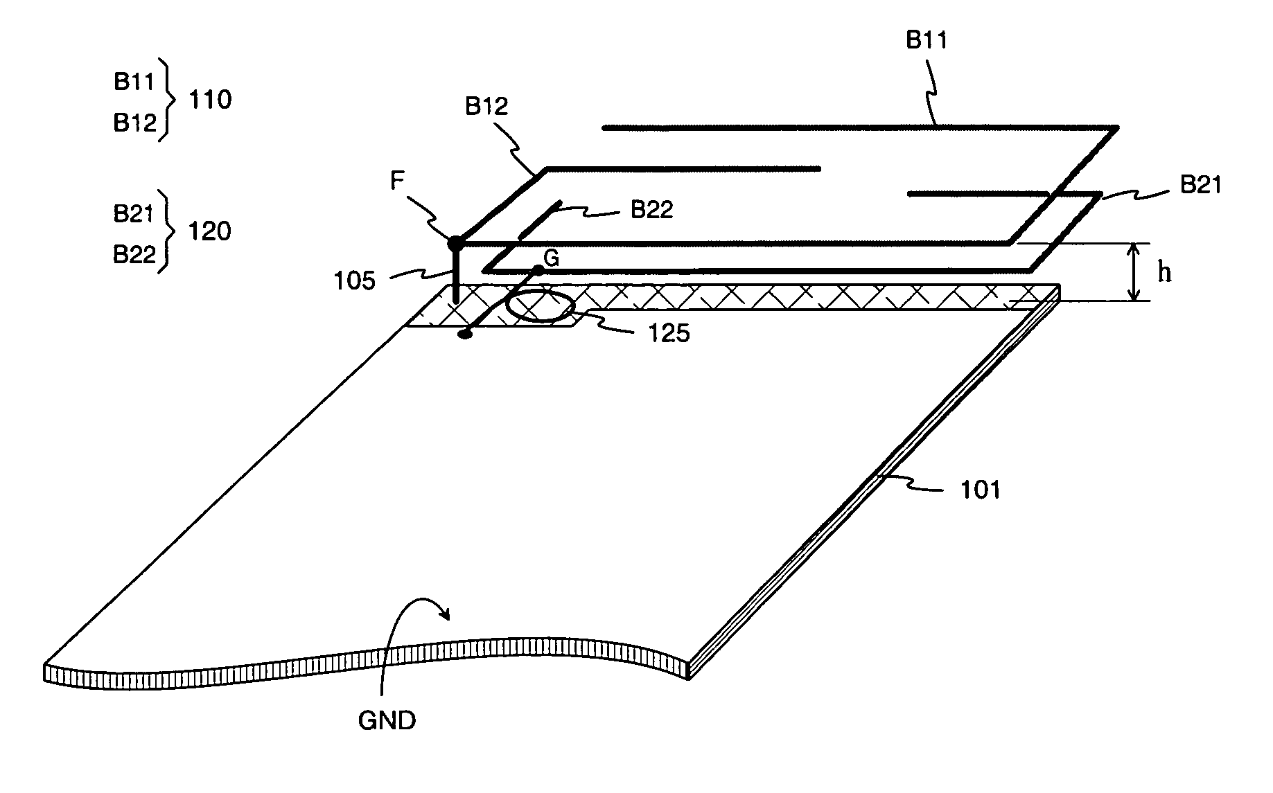
[0016]FIG. 1 shows a first example of an antenna according to the invention. Shown is a radio device circuit board 101 to one end of which an antenna is connected. The main components of the antenna are a base element 110 and parasitic element 120. In this example the base element is a rigid conductive wire resembling an open rectangular ring. In a corner of the base element 110, situating on the circuit board 101 side, there is a feed point F which is connected to the antenna port of the radio device through a feed conductor 105. The antenna port and the transmitter and receiver of the radio device are located on the opposite side of the circuit board 101 and are not visible in FIG. 1. The upper surface of the circuit board is mostly conductive signal ground GND. This, however, does not extend to the antenna, so the base element 110 together with the feed conductor 105 constitute a monopole-type radiator. In this example the monopole radiator has got two bands. Its fundamental reso...


PUM


Abstract

An antenna intended to be used in a small-sized and flat radio device, and to a radio device which has an antenna according to the invention. The base element of the antenna is a monopole-type conductor (110) internal to the device. This conductor may be designed such that the harmonic nearest to the fundamental resonating frequency can be utilized in providing an upper operating band. In addition to the base element the antenna structure comprises a parasitic element (120) which functions as both an auxiliary radiator and antenna matching element. Matching is optimized using an inductive component (125) which connects the parasitic element to signal ground. The antenna gain achieved is considerably higher than that of known antenna structures occupying the same space (h), and the antenna matching is improved, compared to known internal monopole antennas.

Description

[0001]The invention relates to an antenna intended to be used in a small-sized and flat radio device. The invention also relates to a radio device which has an antenna according to the invention.BACKGROUND OF THE INVENTION[0002]Commercial portable radio devices, such as mobile phones, include models with a total device depth of about one centimeter, for example. Such flat structures are especially the folding parts of flip-type mobile phones. A flip phone has got two parts such that the parts can be folded over, on a hinge, so that they lie on top of each other or adjacently end-to-end in almost the same plane. In the first position, the device is particularly small, and it is in the latter position during connection.[0003]Antennas used in flip phones are normally monopole-type external antennas. Their drawback is the inconvenience generally associated with a protruding structural element. Naturally it would be possible to use internal PIFA-type planar antennas, but the thin structu...

Claims


Application Information

Patent Timeline
Patent Type & Authority Patents(United States)
IPC IPC(8): H01Q1/24H01Q5/00H01Q5/371H01Q5/378H01Q5/392H01Q9/04H01Q9/40H01Q9/42H01Q19/00
CPCH01Q1/243H01Q9/0442H01Q9/40H01Q5/392H01Q19/005H01Q5/371H01Q5/378H01Q9/42
Inventor MIKKOLA, JYRKILEPISTO, TOMMI
Owner PULSE FINLAND
Why Eureka
Try Eureka