Apparatus and method for maintaining stability in a disc drive servo loop

Inactive Publication Date: 2006-11-14
SEAGATE TECH LLC
View PDF15 Cites 19 Cited by
  • Summary
  • Abstract
  • Description
  • Claims
  • Application Information

AI Technical Summary

Benefits of technology

[0009]An apparatus and method of maintaining stability in a servo loop of a disc drive is provided. A dither signal (a single frequency sine wave or a multi-frequency signal) is injected int

Problems solved by technology

Such gain variations can degrade the performance of the disc drive and, in some cases, cause intermittent stability problems in the s

Method used


Image

  • Apparatus and method for maintaining stability in a disc drive servo loop
  • Apparatus and method for maintaining stability in a disc drive servo loop
  • Apparatus and method for maintaining stability in a disc drive servo loop

Examples


Embodiment Construction

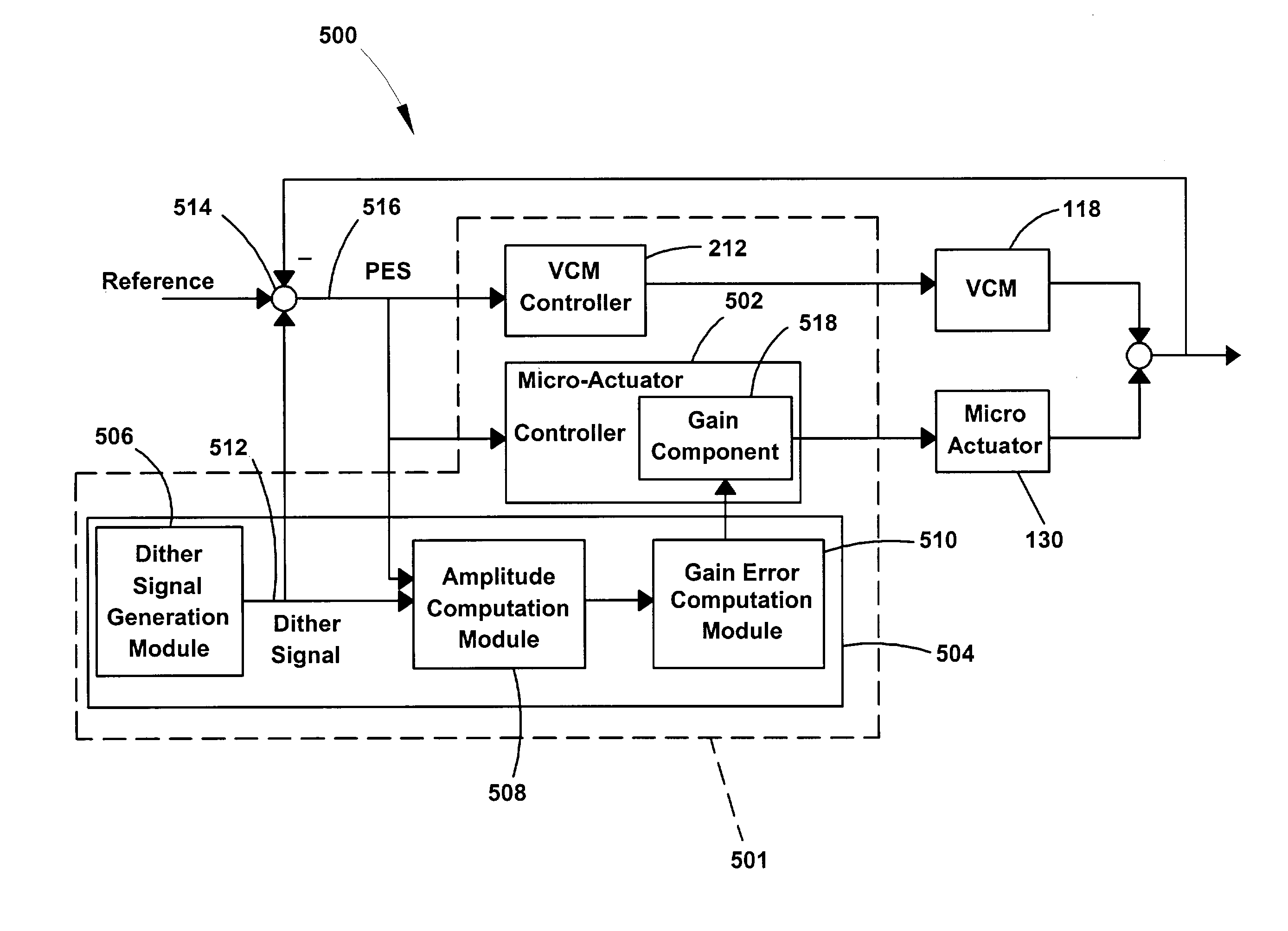
[0017]In the embodiments described below, an apparatus and method are provided for calibrating a gain of a disc drive servo loop in real-time. The real-time gain calibration is carried out by injecting a dither signal into the servo loop and obtaining a servo loop gain error signal in response to the injected dither signal. A gain of the servo loop is adjusted as a function of the servo loop gain error signal.

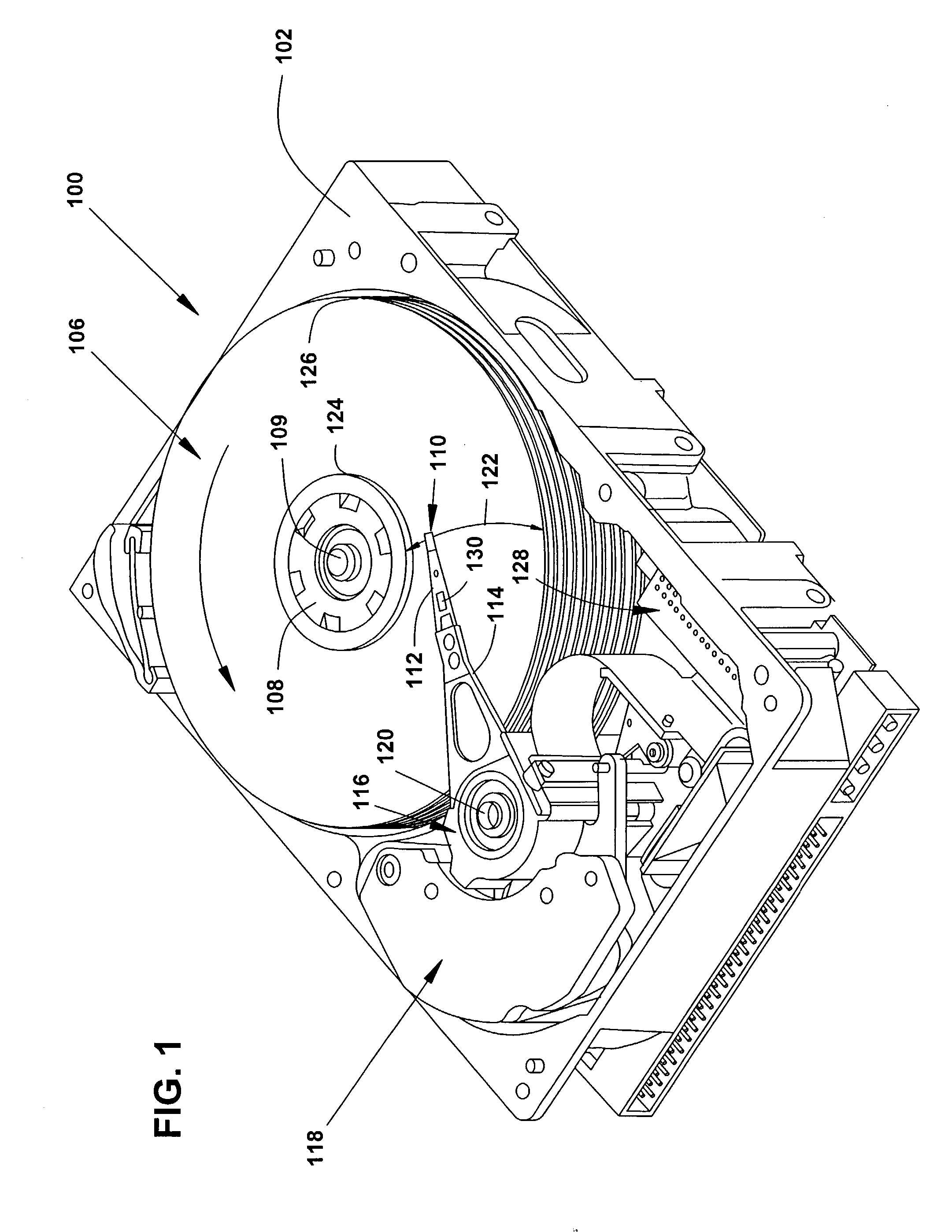
[0018]Referring now to FIG. 1, a perspective view of a disc drive 100 in which the present invention is useful is shown. Disc drive 100 includes a housing with a base 102 and a top cover (not shown). Disc drive 100 further includes a disc pack 106 which is mounted on a spindle motor (not shown) by a disc clamp 108. Disc pack 106 includes a plurality of individual discs, which are mounted for co-rotation about central axis 109. Each disc surface has an associated disc head slider 110 which is mounted to disc drive 100 for communication with the disc surface. In the example shown...


PUM


Abstract

An apparatus and method of maintaining stability in a servo loop of a disc drive is provided. A dither signal (a single frequency sine wave or a multi-frequency signal) is injected into the servo loop. A servo loop gain error signal is obtained in response to the injected dither signal. A gain of the servo loop is adjusted as a function of the servo loop gain error signal in real-time.

Description

FIELD OF THE INVENTION[0001]The present invention is related to disc drives. In particular, the present invention is related to disc drive servo control systems.BACKGROUND OF THE INVENTION[0002]In a computer disc drive, data is stored on discs in concentric tracks.[0003]In disc drives with relatively high track densities, a servo feedback loop is used to maintain a head over the desired track during read or write operations. This is accomplished utilizing prerecorded servo information either on a dedicated servo disc or on sectors that are interspersed along a disc. During track following, the servo information sensed by the head is demodulated to generate a position error signal (PES) which provides an indication of the distance between the head and the track center. The PES is then converted into an actuator control signal, which is used to control an actuator that positions the head.[0004]Historically, only one actuator, typically a voice coil motor (VCM), was used to position th...

Claims


Application Information

Patent Timeline
IPC IPC(8): G11B5/596
CPCG11B5/59622
Inventor ZHANG, TAOMORRIS, JOHN CHRISTOPHERCVANCARA, DUSTIN MARKSOSSEH, RAYE ABDOULIE
Owner SEAGATE TECH LLC
Why Eureka
Try Eureka