Method and apparatus for estimating values for condition indicators

a condition indicator and value estimation technology, applied in the field of vibration analysis, can solve problems such as vibration in the supporting structure, transmission failure, and transmission error, and achieve the effects of increasing the level of te and transmission failur

Active Publication Date: 2006-11-14
SIMMONDS PRECISION PRODS
View PDF21 Cites 78 Cited by
  • Summary
  • Abstract
  • Description
  • Claims
  • Application Information

AI Technical Summary

Benefits of technology

[0008]In accordance with one aspect of the invention are a method executed in a computer system and computer program product for estimating a conditional indicator value associated with a gear pair. The gear pair is modeled as a damped spring model having a contact line between said gears. A force, P, is determined at a point of contact along said contact line causing linear and torsional response to each of said two gears in said gear pair. A relative movement, d, is determined of said gear pair, in accordance with said force, P, as a sum of four responses and a contact deflection, said relative movement d representing a gear model having two degrees of freedom. The relative movement, d, is used in determining said conditional indicator value for transmission error associated with said gear pair.

Problems solved by technology

The transmission of power to rotors which propel helicopters and other shafts that propel devices within the aircraft induce vibrations in the supporting structure.
The vibration is associated with transmission error (TE).
Increased levels of TE are associated with transmission failure.
The replacement schedules may indicate replacement time intervals that are too aggressive resulting in needless replacement of working parts.
This may result in incurring unnecessary costs as airplane parts are expensive.
Additionally, new equipment may have installed faulty or defective parts that may fail prematurely.

Method used


Image

  • Method and apparatus for estimating values for condition indicators
  • Method and apparatus for estimating values for condition indicators
  • Method and apparatus for estimating values for condition indicators

Examples


Embodiment Construction

)

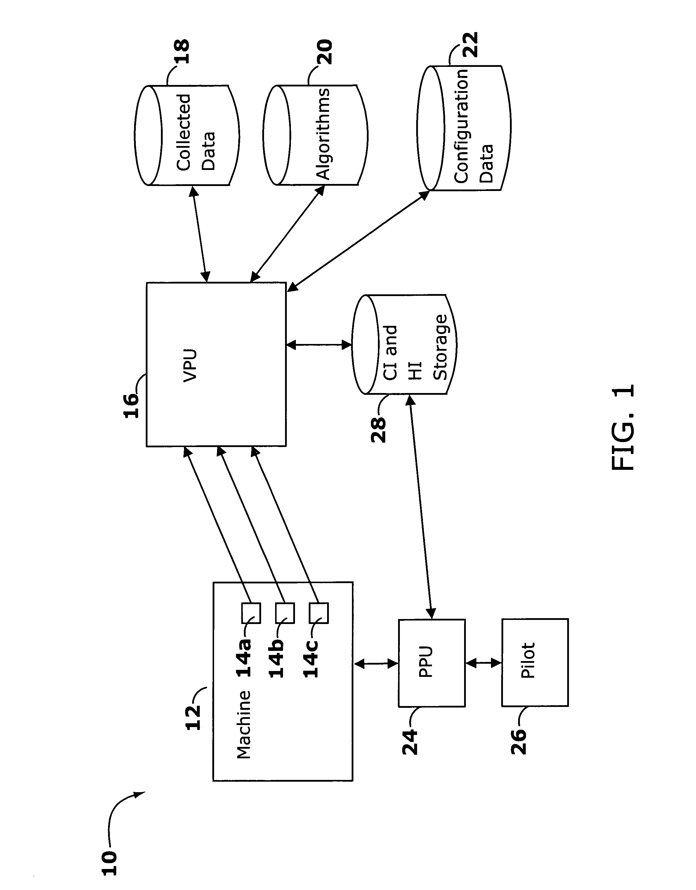
[0047]Referring now to FIG. 1, shown is an example of an embodiment of a system 10 that may be used in performing vibration analysis and monitoring of a machine such as a portion of an aircraft. The machine being monitored 12 may be a particular element within an aircraft. Sensors 14a through 14c are located on the machine to gather data from one or more components of the machine. Data may be collected by the sensors 14a through 14c and sent to a processor or a VPU16 for data gathering and analysis. The VPU16 analyzes and gathers the data from the Sensors 14a through 14c.

[0048]The VPU16 may also use other data in performing analysis. For example, the VPU16 may use collected data 18. One or more of the Algorithms 20 may be used as input into the VPU16 in connection with analyzing data such as may be gathered from the Sensors 14a through 14c. Additionally, configuration data 22 may be used by the VPU16 in connection with performing an analysis of the data received for example from t...


PUM

PropertyMeasurementUnit
degrees of freedomaaaaaaaaaa
mean failure timeaaaaaaaaaa
forceaaaaaaaaaa

Abstract

Disclosed are techniques used in connection with determining a health indicator (HI) of a component, such as that of an aircraft component. The HI is determined using condition indicators (CIs) which parameterize characteristics about a component minimizing possibility of a false alarm. Different algorithms are disclosed which may be used in determining one or more CIs. The HI may be determined using a normalized CI value. Techniques are also described in connection with selecting particular CIs that provide for maximizing separation between HI classifications. Given a particular HI at a point in time for a component, techniques are described for predicting a future state or health of the component using the Kalmán filter. Techniques are described for estimating data values as an alternative to performing data acquisitions, as may be used when there is no pre-existing data.

Description

CROSS REFERENCE TO RELATED APPLICATIONS[0001]This application claims priority to U.S. Provisional patent application No. 60 / 293,331 filed on May 24, 2001 which is incorporated by reference herein.BACKGROUND OF THE INVENTION[0002]1. Field of the Invention[0003]This application relates to the field of vibration analysis and more particularly to performing vibration analysis for the purpose of device monitoring.[0004]2. Description of Related Art[0005]The transmission of power to rotors which propel helicopters and other shafts that propel devices within the aircraft induce vibrations in the supporting structure. The vibrations occur at frequencies that correspond to the shaft rotation rate, mesh rate, bearing passing frequency, and harmonics thereof. The vibration is associated with transmission error (TE). Increased levels of TE are associated with transmission failure. Similar types of vibrations are produced by transmissions in fixed installations as well.[0006]Parts, such as those...

Claims


Application Information

Patent Timeline
Patent Type & Authority Patents(United States)
IPC IPC(8): G06G7/48G01H1/00G01N29/11G01N29/12G01N29/44G01N29/46G05B23/02
CPCG01H1/003G01N29/11G01N29/12G01N29/4445G01N29/449G01N29/46G05B23/0221G05B23/0235G05B23/0254G01N2291/2693G01N2291/2696
Inventor BECHHOEFER, ERIC ROBERT
Owner SIMMONDS PRECISION PRODS
Why Eureka
Try Eureka