
Control for diesel engine with particulate filter

a technology of particulate filter and control method, which is applied in the direction of electric control, machines/engines, mechanical equipment, etc., can solve the problems of excessive temperature degrading of dpf, unnecessary energy use, and recognition of disadvantages, so as to limit exothermic reaction and limit exothermic reaction rate , prevent over temperature conditions

Active Publication Date: 2006-11-21
FORD GLOBAL TECH LLC
View PDF22 Cites 53 Cited by
  • Summary
  • Abstract
  • Description
  • Claims
  • Application Information

AI Technical Summary

Benefits of technology

[0009]A method for regenerating a particulate filter coupled to an internal combustion engine, comprising: commencing a self-sustaining filter regeneration; monitoring whether said regeneration causes temperature of said particulate filter to become greater than a predetermined value; in response to said monitoring, adjusting one or more operating parameters so as to limit exothermic reaction via control of an oxygen amount entering said filter and prevent temperature from rising to become greater than a pre-selected value.
[0010]Thus, according to the present invention, it is possible to exploit self-sustaining particulate filter regeneration, without suffering degradation of the particulate filter due to excessive temperatures. In other words, by limiting excess oxygen entering the particulate filter, which thereby limits the exothermic reaction rate, it is possible to prevent over temperature conditions that might otherwise occur due to the self-sustaining reaction.

Problems solved by technology

In other words, it may become unnecessary to use energy, for example, in a burner, to maintain high DPF temperatures sufficient to maintain regeneration.
However, the inventors herein have also recognized a disadvantage with the above approach.
In particular, while self-sustained regeneration can decrease a fuel economy penalty, it can cause other disadvantages.
In particular, if the reaction rate is too high, the combustion of soot on the filter may result in excessive temperatures that degrade the DPF.
Finally, the inventors have realized that relying on exhaust air flow alone to carry heat away from the DPF may not provide sufficient cooling.
In particular, it may not be clear ahead of time if a certain operating condition will allow enough air flow to cool the DPF.

Method used


Image

  • Control for diesel engine with particulate filter
  • Control for diesel engine with particulate filter
  • Control for diesel engine with particulate filter

Examples


Embodiment Construction

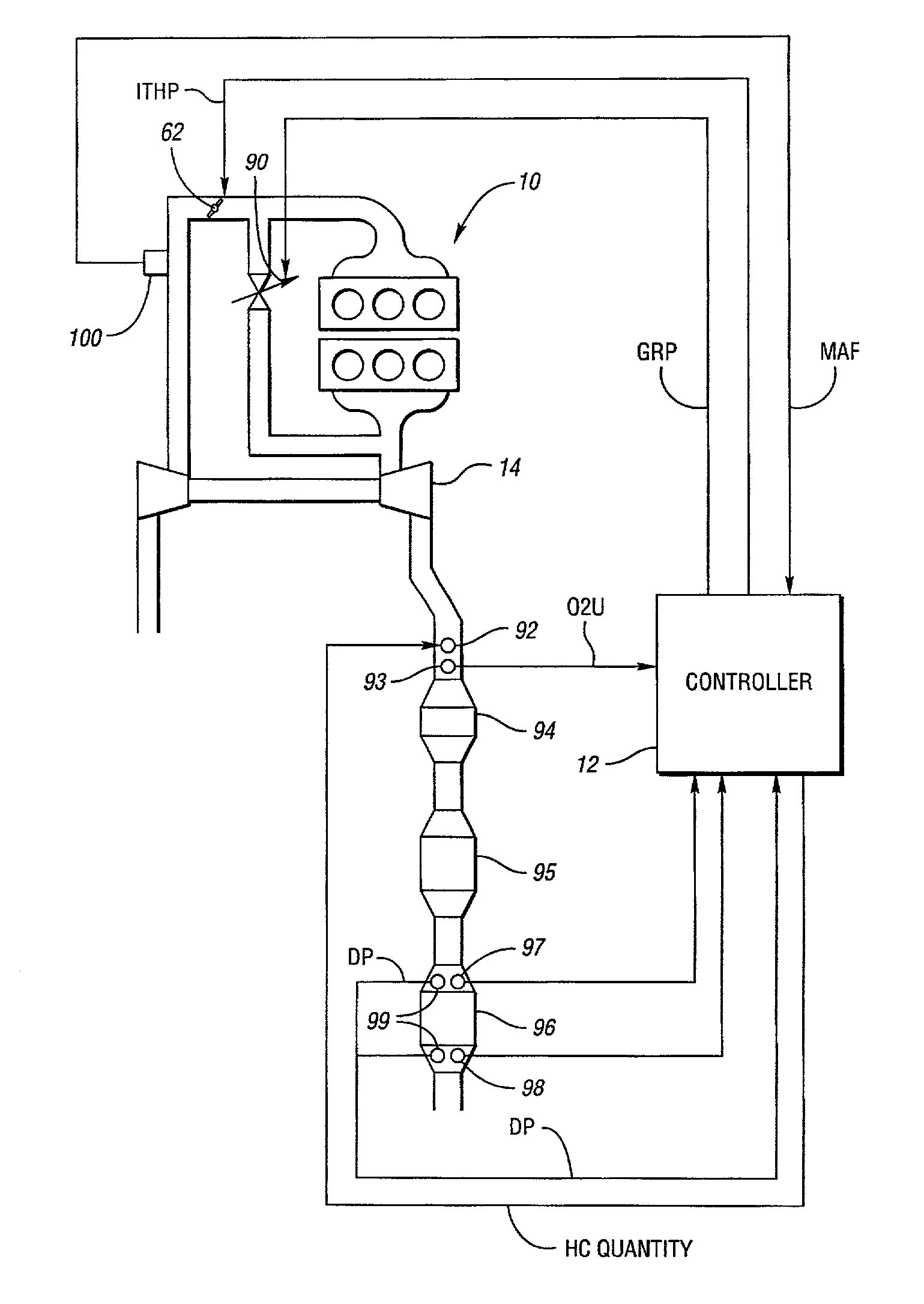
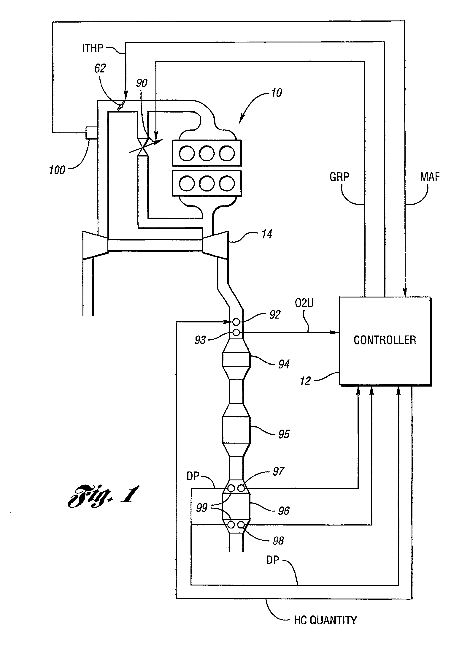
[0018]Referring now to FIG. 1, a schematic diagram of the engine system is described. Engine 10 is shown coupled to a turbo charger 14. Turbo charger 14 can be any number of types, including a single stage turbo charge, a variable geometry turbo charger, a dual fixed geometry (one for each bank), or a dual variable geometry turbo charger (one for each bank).

[0019]Intake throttle 62 is shown for controlling manifold pressure and air flow entering the engine 10. In addition, EGR valve 90 is shown for controlling recirculated exhaust gas entering the intake manifold of engine 10. In the exhaust system, downstream of turbocharger 2 is HC injector 92. Also located downstream of injector 92 is an oxygen sensor 93, which provides signal O2U. Downstream of oxygen sensor 93 is located a first oxidation catalyst 94. A second oxidation catalyst 95 may also be used but may also be eliminated. The oxidation catalyst can be of various types, such as, for example, an active lean NOx catalyst.

[0020...


PUM


Abstract

A system and method are described for operating a diesel engine and particulate filter during self-sustained filter regeneration. In particular, a method is described for preventing over-temperature during filter regeneration by limiting excess oxygen supplied to the particulate filter.

Description

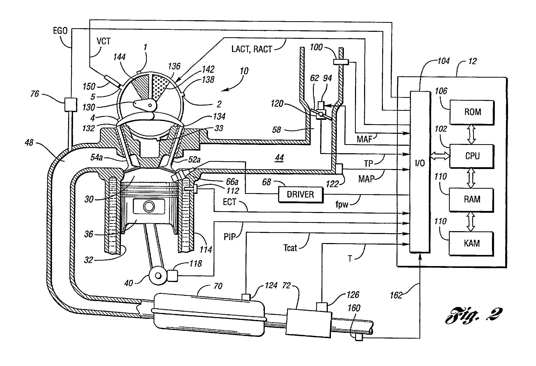
BACKGROUND OF INVENTION[0001]1. Field of the Invention[0002]The present invention relates to engine control strategies for engines and, more particularly, control methods for diesel engines having a diesel particulate filter (DPF).[0003]2. Background Art[0004]Diesel particulate filters (DPFs) are typically used in diesel engines. These filters store particulates generated by engine combustion. When the filter is raised above a predetermined temperature, the retained particles, which are mostly in the form of carbon, are burned off. After a majority of the particles are burned off, the filter can again retain particles generated by the engine.[0005]There are various methods to raise and sustain particulate filter temperature to allow the above-described regeneration. For example, a burner can be used to burn fuel and thereby generate heat. Further, the burner can be controlled based on engine speed and load and temperature as described in U.S. Pat. No. 5,044,158. It is also known tha...

Claims


Application Information

Patent Timeline
IPC IPC(8): F01N3/00F01N3/025F01N13/02F02B37/00F02D41/00F02D41/02
CPCF01N3/0253F02D41/0002F02D41/029F01N13/0093F01N13/009F01N2250/02F01N2570/14F02B37/00F02D2041/001F02D2200/0802Y02T10/42Y02T10/40
Inventor VAN NIEUWSTADT, MICHIEL J.BREWBAKER, TOM ALAN
Owner FORD GLOBAL TECH LLC
Learn More