Fan apparatus, method of manufacturing fan apparatus, projection type display device and electronic device

a technology of fan apparatus and fan body, which is applied in the direction of wind motors with parallel air flow, liquid fuel engine components, non-positive displacement fluid engines, etc., can solve the problems of limiting the downsizing or price reduction of the apparatus, loud noise, and interference with audiovisual functions, so as to achieve the effect of fewer parts

Inactive Publication Date: 2006-11-21
PANASONIC CORP
View PDF37 Cites 10 Cited by
  • Summary
  • Abstract
  • Description
  • Claims
  • Application Information

AI Technical Summary

Benefits of technology

[0013]In view of the above-described problems, it is an object of the present invention to provide a fan apparatus, method of manufacturing the fan apparatus, projection type display device, and electronic device, eliminating the need for any light-shielding member and with fewer parts.

Problems solved by technology

However, such a conventional projection type display device requires a large light-shielding member to prevent light from leaking toward the outside of the set through the exhaust opening that circulates exhaust air of the cooling fan, which constitutes a major limiting factor against downsizing or price-reduction of the apparatus.
Furthermore, the above-described conventional projection type display device has excessive air blowing resistance of the cooling fan caused by such a light-shielding member, which requires high-speed drive of the cooling fan to cope with an increased amount of heat generated at the high-power light source lamp unit, producing loud noise and interfering with audiovisual functions.

Method used


Image

  • Fan apparatus, method of manufacturing fan apparatus, projection type display device and electronic device
  • Fan apparatus, method of manufacturing fan apparatus, projection type display device and electronic device
  • Fan apparatus, method of manufacturing fan apparatus, projection type display device and electronic device

Examples


embodiment 1

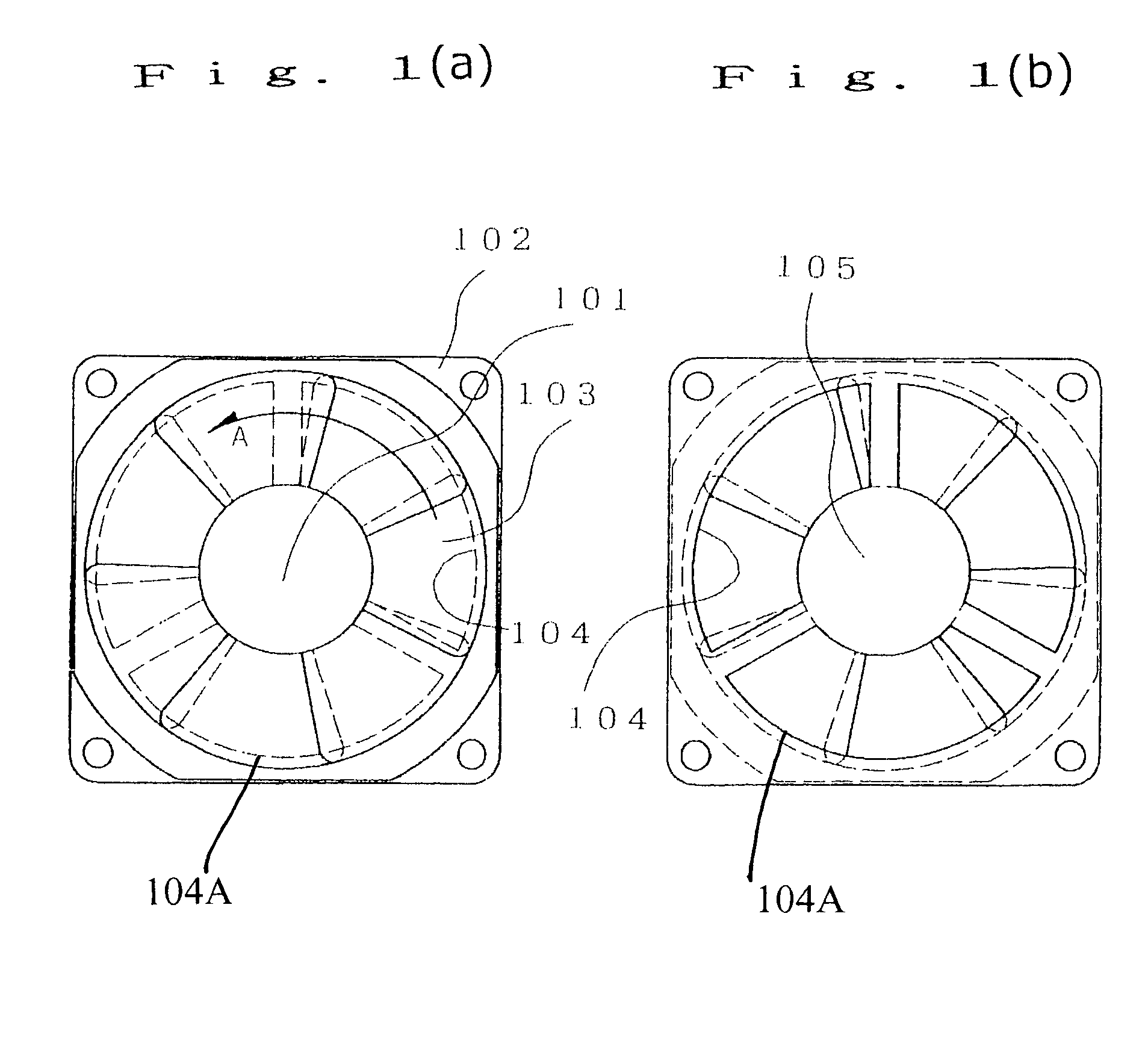
[0077]First, with reference to mainly FIGS. 1(a) and (b) a configuration of an axial flow fan of this embodiment will be explained. FIG. 1(a) illustrates an axial flow fan according to Embodiment 1 of the present invention viewed from the air intake side along the axial direction and FIG. 1(b) illustrates an axial flow fan according to Embodiment 1 of the present invention viewed from the air exhaust side along the axial direction.

[0078]In FIGS. 1(a) and 1(b), the rotation center on the stator side of a motor 101 which is a rotation drive source is fixed to the center of a motor support frame provided in a plurality of spokes without interrupting the air flow, using a housing 102 which serves as the housing of the fan.

[0079]A plurality of propeller blades 103 formed integral with the outer radius side of the rotor which constitutes a rotator of the motor 101 provide the means of blowing air. The propeller blades 103 are formed in such a way that mutually neighboring propeller blades...

embodiment 2

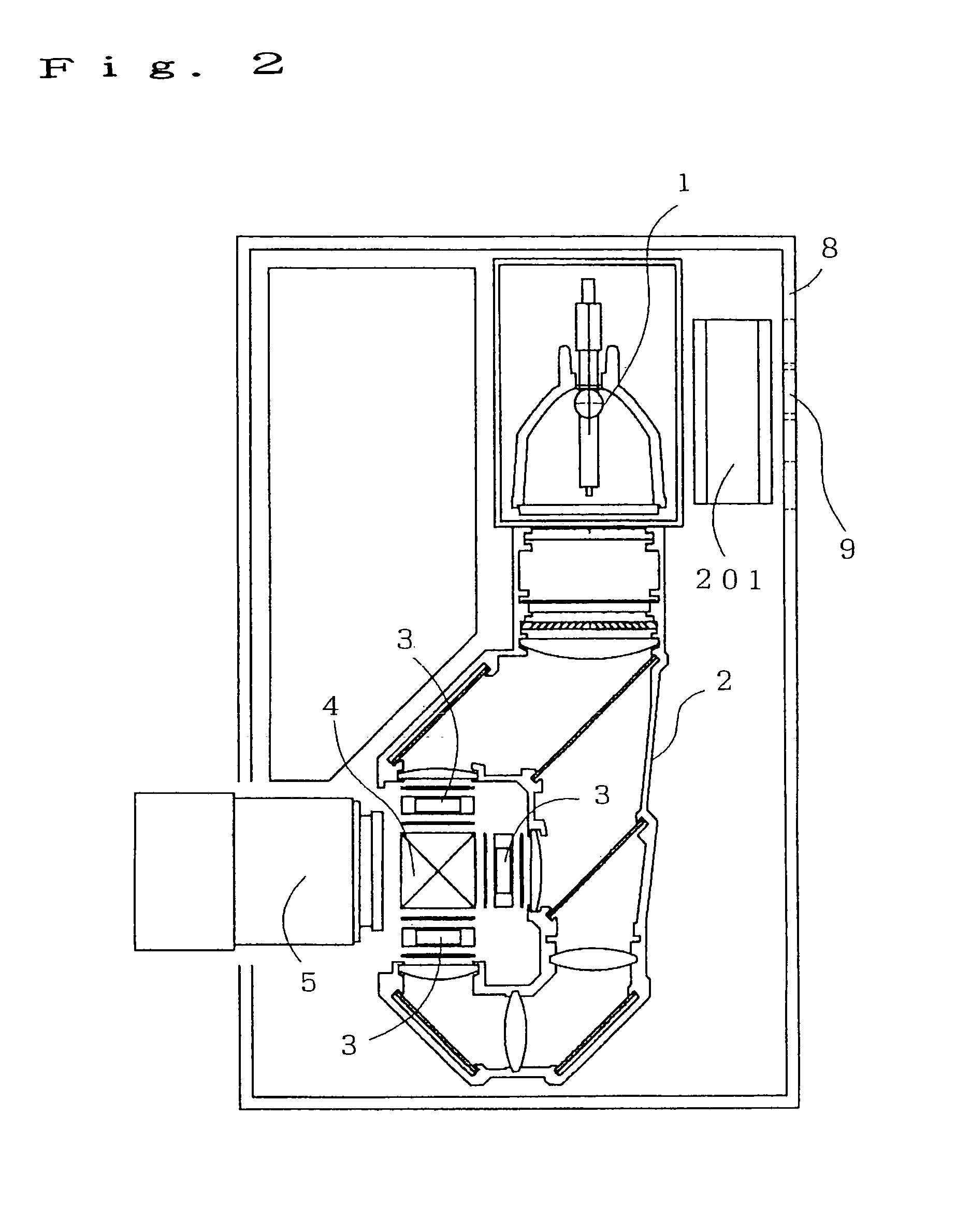
[0088]First, a configuration of a projection type display device of this embodiment will be explained mainly with reference to FIGS. 2 and 3. FIG. 2 is a plan view of a projection type display device according to Embodiment 2 of the present invention and FIG. 3 is a right side view of a projection type display device according to Embodiment 2 of the present invention.

[0089]Here, the same means as the means of a conventional projection type display device (see FIGS. 6 and 7) are assigned the same reference numerals.

[0090]FIG. 2 shows a projection type display device provided with a light source lamp unit 1, an irradiation optical unit 2 that condenses light from the above-described light source lamp unit 1, three liquid crystal panel units 3 consisting of R, G and B liquid crystal panels for optically generating image information from the condensed light, a color combination system unit 4 that color-combines the optical information of the liquid crystal panel units 3, a projection op...

embodiment 3

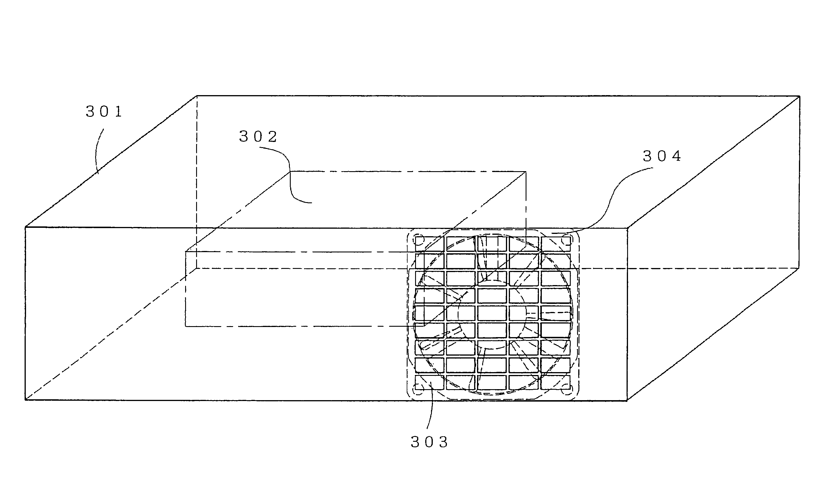
[0102]First, a configuration of an electronic device of this embodiment will be explained mainly with reference to FIG. 4. FIG. 4, is a perspective view of the electronic device according to Embodiment 3 of the present invention.

[0103]A housing 301 is a housing of an electronic device such as a personal computer.

[0104]Inside the housing 301 is one or a plurality of heating members 302 having such a large amount of heat generated that requires cooling at least by forced air cooling. For example, a circuit board with a drive IC mounted and CPU, etc., correspond to this heating material.

[0105]The housing 301 is provided with an air intake opening (not shown) to take in air outside the housing 301 and an exhaust opening 303 to exhaust a high temperature atmosphere from the interior of the housing 301.

[0106]An axial flow fan 304 is an axial flow fan for forced air cooling having the same configuration as that of the axial flow fan explained in the above-described Embodiment 1.

[0107]The e...


PUM

PropertyMeasurementUnit
opticalaaaaaaaaaa
distanceaaaaaaaaaa
colorsaaaaaaaaaa

Abstract

With a trend toward a higher intensity projection type liquid crystal display device to further increase brightness of a projection screen, rated input power of a light source lamp increases, which makes essential a fan apparatus for cooling the light source lamp, etc. Such a fan apparatus would require a light-shielding member which causes the number of parts to increase. The present invention provides a fan apparatus provided with a rotor section that can be rotated/driven around a predetermined rotation axis and a propeller section including propeller blades and attached to the rotor section arranged in such a way as to substantially shield light parallel to the rotation axis.

Description

[0001]THIS APPLICATION IS A U.S. NATIONAL PHASE APPLICATION OF PCT INTERNATIONAL APPLICATION PCT / JP02 / 08637.TECHNICAL FIELD[0002]The present invention relates to a fan apparatus, method of manufacturing the fan apparatus, projection type display device and electronic device applicable for the purpose of cooling an electronic device such as a projection type display device. The projection type display device may be of the kind that decomposes white light from a light source lamp into light beams of three colors; red, blue and green, and lets each light beam pass through a light bulb composed of, for example, a liquid crystal panel. The light beams are then modulated according to image information, color-combined after modulation and then enlarged and projected onto a screen through a projection lens unit.BACKGROUND ART[0003]For a projection type liquid crystal display device in recent years, a high resolution light bulb device, for example, a liquid crystal panel unit is used to proj...

Claims


Application Information

Patent Timeline
Patent Type & Authority Patents(United States)
IPC IPC(8): G03B21/16F03B3/12F21V29/00G02F1/1333H04N5/74F04D29/32G02F1/133
CPCF04D29/325G03B21/16G02F1/133385
Inventor KAWAHARA, SHOJIOKADA, TAKEHIROHOSHINO, MAKOTOYOSHIOKA, KOJI
Owner PANASONIC CORP
Why Eureka
Try Eureka