Connector

a technology of connecting rods and connectors, applied in the direction of coupling contact members, coupling device connections, two-part coupling devices, etc., can solve the problems of complicated element construction, large connecting rods, and restricted assembly order, so as to improve reliability in time of use

Inactive Publication Date: 2006-11-21
HOSIDEN CORP
View PDF12 Cites 30 Cited by
  • Summary
  • Abstract
  • Description
  • Claims
  • Application Information

AI Technical Summary

Benefits of technology

[0010]Thus, the main connector body insulates and holds the plurality of contact members arranged at intervals in the direction of width, and the two board ends to be connected are inserted into the main connector body to place the land electrodes of each board end in pressure contact with the points of contact in each end region of the contact members. This construction can achieve compactness and space saving by reducing the intervals at which the contact members are juxtaposed, despite an increase in the number of contact members for coping with multiple electrodes. The element construction is simple in that only the two elements, i.e. the contact members and the main connector body, are required, which achieves a reduction in die cost. Further, the two board ends have only to be placed in pressure contact with the respective contact members, without requiring solder mounting, which eliminates the restriction as to the order of mounting the board ends. In the case, for example, of an apparatus set having a plurality of units finally assembled after being manufactured in different locations, the flexibility of unit manufacture may be improved.
[0037]Thus, a preferred embodiment of the connector is provided which does not allow the board ends inserted in the connector to become detached with ease, thereby improving reliability in time of use.

Problems solved by technology

This results in disadvantages of the connectors becoming large in time of increasing electrodes, and a complicated element construction.
There is also a disadvantage of an assembling order being restricted since it is necessary to perform the solder mounting step first.

Method used


Image

  • Connector
  • Connector
  • Connector

Examples


Embodiment Construction

[0048]An embodiment of the present invention will be described hereinafter with reference to the drawings.

[0049]An embodiment of a connector according to the present invention will be described with reference to the drawings.

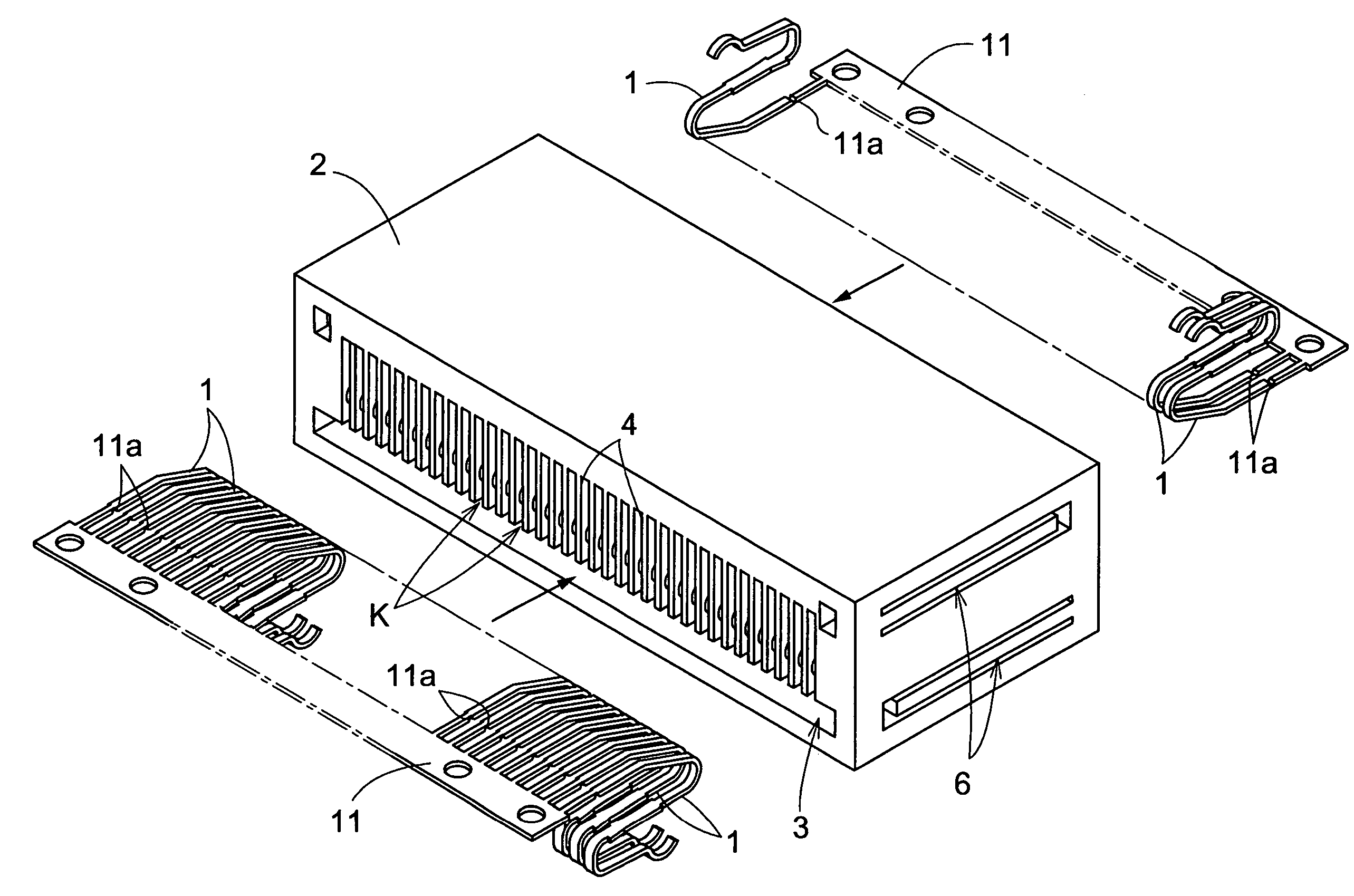
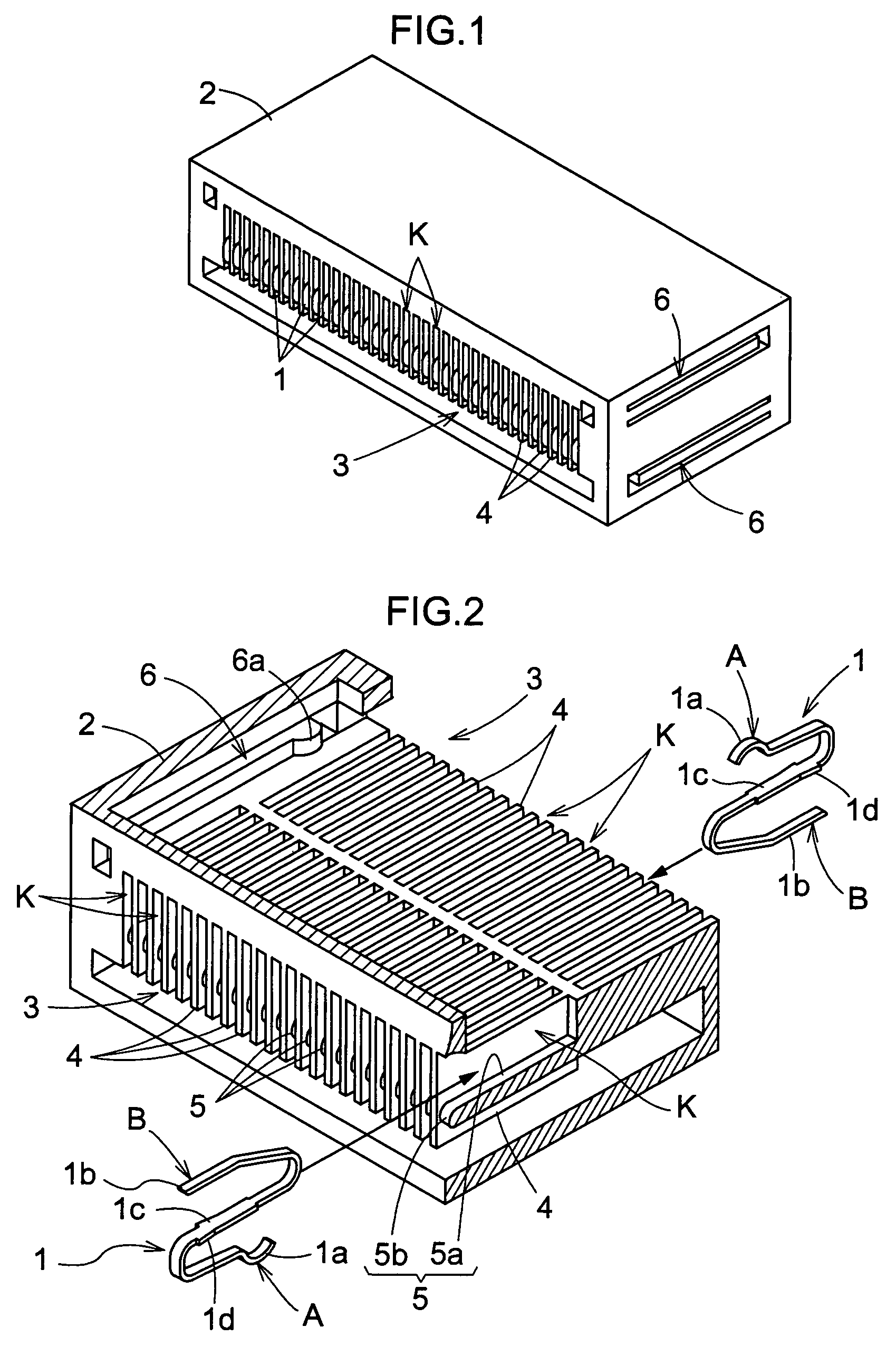
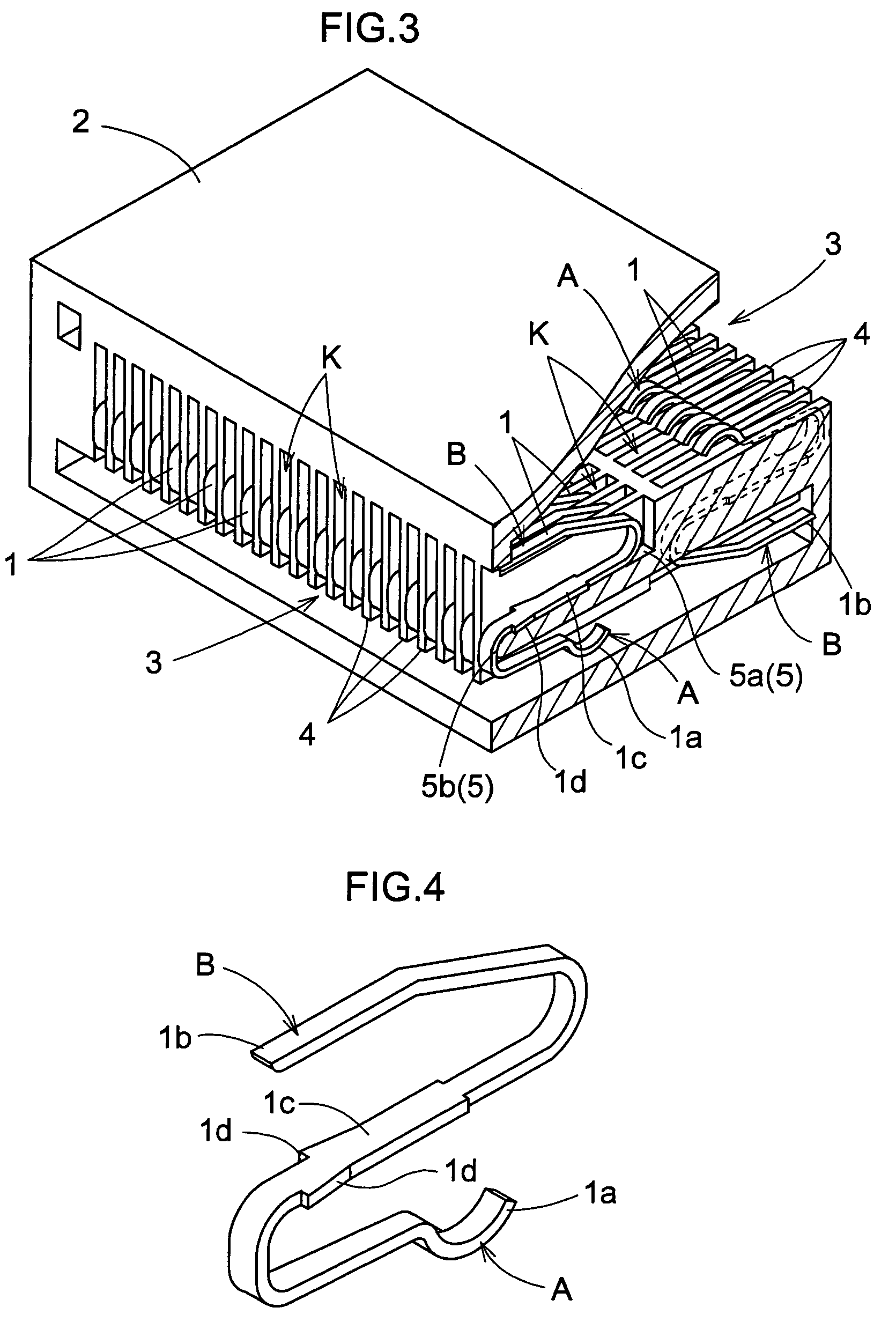
[0050]As shown in FIGS. 1–4, 5 (a), 5 (b), 5 (c), 6 (a) and 6 (b), the connector according to this invention includes contact members 1 having elastically deformable points of contact A and B formed in two locations, and a main connector body 2 for insulating and holding a plurality of contact members 1 arranged at intervals in a width direction with the two points of contact A and B of the respective contact members 1 being in the same positions as seen in the direction of arrangement. FIG. 5 (b) is a cross section taken on line X—X shown in FIG. 5 (a), FIGS. 6 (a) and 6 (b) are views in vertical section taken on line Y—Y shown in FIG. 5 (a).

[0051]The above main connector body 2 has a pair of socket portions 3 for receiving board ends 10 defining land electrode...


PUM


Abstract

Disclosed are contact members which have elastically deformable points of contact formed in two locations, and a main connector body for insulating and holding a plurality of contact members arranged at intervals in a width direction with the points of contact in the two locations of the respective contact members being in the same positions as seen in the direction of arrangement. The main connector body includes a pair of socket portions for receiving board ends defining land electrodes in two rows corresponding to the points of contact of the respective contact members lying in the same positions as seen in the direction of arrangement, so that the land electrodes are in pressure contact with the corresponding points of contact.

Description

TECHNICAL FIELD[0001]The present invention relates to a connector for connecting printed circuit boards, flexible printed wiring boards (hereinafter abbreviated to FPC), or a printed circuit board and an FPC, for example.BACKGROUND ART[0002]As shown in FIGS. 10 (a), 10 (b) and 10 (c), the above connector is used, for example, in a bending part (hinged part) of a folding type cell phone for connecting printed circuit boards in an upper case and a lower case. Specifically, in Example 1 in FIG. 10 (b), male connectors attached to the opposite ends of an FPC are inserted in female connectors with terminals thereof soldered to ends of the circuit boards in the respective cases (see Japanese Patent Publication “Kokai” No. 9-82439 (pages 4–6, FIGS. 1–14), for example). In Example 2 in FIG. 10 (c), electrodes formed at opposite ends of an FPC are inserted in female connectors with terminals thereof soldered to ends of the circuit boards in the respective cases (see Japanese Patent Publicati...

Claims


Application Information

Patent Timeline
Patent Type & Authority Patents(United States)
IPC IPC(8): H01R24/00H01R12/61H01R12/71H01R12/72H01R12/78H01R12/79H01R13/24H01R31/06H01R35/04
CPCH01R13/2435H01R12/721H01R12/79H01R12/714H01R12/58
Inventor NAGATA, TAKAYUKI
Owner HOSIDEN CORP
Why Eureka
Try Eureka